Copper Clad Laminate (CCL) for LED PCBs: Sourcing, Specifications and Cost Control

On This Page (Table of Contents)
An LED board can pass the first factory test and still fail early in the field.
One common reason is a poor match between the design requirements and the copper clad laminate, or CCL, used as the base material beneath the circuit.
If you source LED lighting products, you probably do not need a chemistry lesson. But you do need to know how raw board specifications affect final cost, SMT assembly yield, heat dissipation, and long-term reliability.
Most buyers focus on LED chips, drivers, and optics. The base laminate is quieter, but it still decides whether the LEDs stay cool and whether the finished board can survive mass production.
This guide explains what copper clad laminate is, how it becomes a finished PCB, which CCL types matter for LED lighting, and what specifications to prepare before requesting an aluminum PCB quote.
What Is Copper Clad Laminate (CCL) in PCB Manufacturing?
Copper clad laminate is the raw copper-covered base sheet used to manufacture printed circuit boards.
Think of CCL as the starting panel that a PCB factory buys before drilling holes, imaging circuits, etching copper, adding solder mask, and routing the final board shape.
A raw sheet of CCL is usually made from an insulating base material with copper foil bonded to one or both sides. The fabricator patterns your circuit design onto the copper and removes unwanted copper by etching. The copper that remains becomes the conductive traces and pads of the finished PCB.
In rigid PCB material standards and supplier datasheets, CCL is normally described by its base material, copper cladding, copper weight, thickness, thermal properties, and electrical insulation performance. For buyers, the practical point is simple:
No suitable CCL, no reliable PCB.
For standard LED boards such as linear lighting modules, downlights, and light strips, single-sided aluminum-based CCL is often the starting material. The aluminum PCB manufacturing process turns this raw stock into a finished board with copper circuits, solder mask, surface finish, and routed outline.
Anatomy of a Copper Clad Laminate: Main Components
A standard CCL sheet looks like one solid material, but it is really a bonded stack designed for electrical, mechanical, and thermal performance.
The main components are:
- Copper foil: The conductive layer where traces and pads are formed. Common copper weights include 0.5 oz, 1 oz, and 2 oz, roughly equal to 17 um, 35 um, and 70 um.
- Insulating substrate or dielectric: The non-conductive material that provides electrical isolation and mechanical structure.
- Resin system: The polymer system that bonds the reinforcement and copper together and affects heat resistance, moisture behavior, and soldering stability.
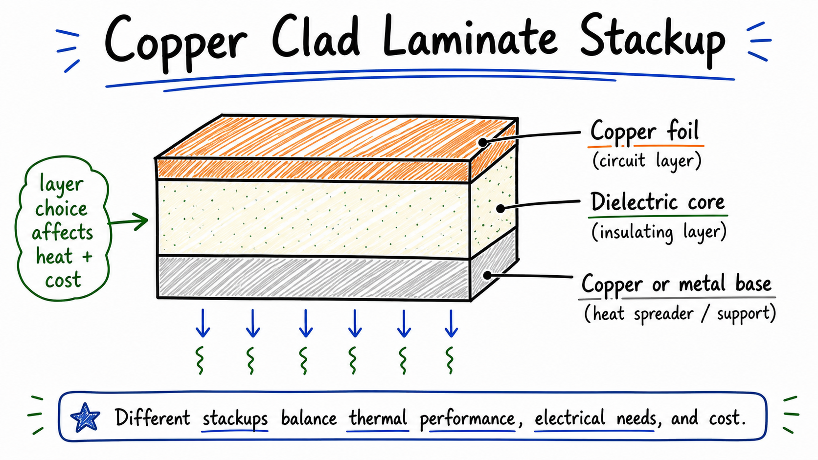 A simplified CCL stackup showing the copper foil, insulating core, and bonded backing layer.
Here is what many buyers miss: resin and dielectric quality directly affect production yield.
If the material cannot handle lead-free SMT reflow, thermal cycling, or the required insulation voltage, the risk is not just a technical datasheet issue. It can become delamination, solder joint stress, scrap, rework, or field failure.
Before choosing a material family, it helps to review broader PCB material selection options and understand how different cores behave under heat, voltage, and assembly stress.
CCL vs. PCB vs. Prepreg vs. Blank Copper Clad Board
Procurement terms can become confusing because suppliers, engineers, and hobby markets often use similar words for different things.
Here is the clean distinction.
CCL, or copper clad laminate, is the fully cured raw sheet with copper bonded to the base material. PCB factories source it as a production input.
Prepreg is a partially cured resin-fiber bonding material used in multilayer PCB lamination. It is not the same thing as a finished laminate sheet.
Blank copper clad board usually refers to an unetched copper-covered panel sold for prototyping or manual etching. It is common in DIY electronics but not the right procurement object for industrial LED PCB orders.
Finished PCB is the manufactured circuit board with drilled holes, etched copper, solder mask, surface finish, and routed outline. This is what most buyers actually order.
| Term | Physical State | Role in Manufacturing | Procurement Object? |
|---|---|---|---|
| Copper clad laminate (CCL) | Fully cured copper-clad raw sheet | Starting material for PCB fabrication | Usually specified through the PCB factory |
| Prepreg | Partially cured resin-fiber sheet | Bonding layer in multilayer construction | Usually specified by the PCB factory |
| Blank copper clad board | Unetched panel | Manual etching or prototyping | Not for normal industrial orders |
| Finished PCB | Fully fabricated circuit board | Ready for assembly or shipment | Yes, this is what buyers usually order |
B2B buyers normally do not purchase raw CCL directly. They define finished board requirements such as board thickness, copper weight, surface finish, thermal conductivity, breakdown voltage, solder mask color, and quantity. The PCB manufacturer then sources a qualifying laminate for production.
Common Types of Copper Clad Laminate in PCB Manufacturing
Not all laminates are built for the same job. CCL can be classified by reinforcement, resin system, electrical performance, and backing material.
FR-4 uses woven glass fabric and epoxy resin. It is the default rigid PCB laminate for many electronics. FR-4 offers a good balance of electrical insulation, mechanical strength, cost, and availability, but it is not an efficient heat-spreading material by itself.
CEM-3 is a composite epoxy material often used as a cost-sensitive alternative for certain rigid boards. It can be useful for simpler LED driver boards where thermal demands are moderate and aluminum base material is not required.
Paper phenolic laminates, such as FR-1 and FR-2, use paper reinforcement with phenolic resin. They are low-cost materials for simple boards, but they are usually not suitable for commercial LED lighting products that require stable soldering and thermal reliability.
Flexible CCL uses flexible films such as polyimide. It is used for flex circuits, not standard rigid LED aluminum boards.
High-frequency laminates use low-loss specialty materials for RF, microwave, or high-speed signal designs. These are expensive and usually outside the needs of standard LED lighting PCBs.
Metal-backed or aluminum CCL places a metal carrier, usually aluminum, below the dielectric and copper circuit layer. This is the key material family for LED aluminum PCBs and many metal core PCB applications.
| Substrate Type | Primary Benefit | Main Limitation | Typical LED Use Case |
|---|---|---|---|
| FR-4 | Widely available, balanced cost and strength | Poor heat spreading compared with metal core materials | LED driver boards, low-power control boards |
| CEM-3 | Cost-effective, suitable for some simple rigid boards | Lower performance margin than FR-4 in demanding conditions | Cost-sensitive control boards |
| Paper phenolic | Very low cost | Limited thermal and mechanical stability | Not recommended for most commercial LED lighting |
| Aluminum-backed CCL | Better heat spreading through metal base | Usually limited to simpler routing than multilayer FR-4 | LED strips, downlights, spotlights, modules |
For related material choices, see single layer PCB board and metal core PCB.
Why LED Lighting Boards Often Use Aluminum-Based CCL
Standard FR-4 is a strong electrical insulator, but it does not spread heat well. For low-power indicator LEDs, that may be acceptable. For high-power downlights, spotlights, panel lights, or high-bay lighting, trapped heat can reduce efficiency, accelerate lumen depreciation, and shorten service life.
Aluminum-based CCL, also called IMS or insulated metal substrate material, helps by creating a shorter thermal path from the LED pad into a metal base.
A typical LED aluminum PCB heat path works like this:
- The LED sits on the solder pad on the copper circuit layer.
- Heat moves from the LED package through the solder joint into the copper.
- Heat crosses the thermally conductive dielectric layer.
- Heat spreads across the aluminum base.
- Heat transfers into the heatsink or luminaire housing through the mechanical stack and thermal interface.
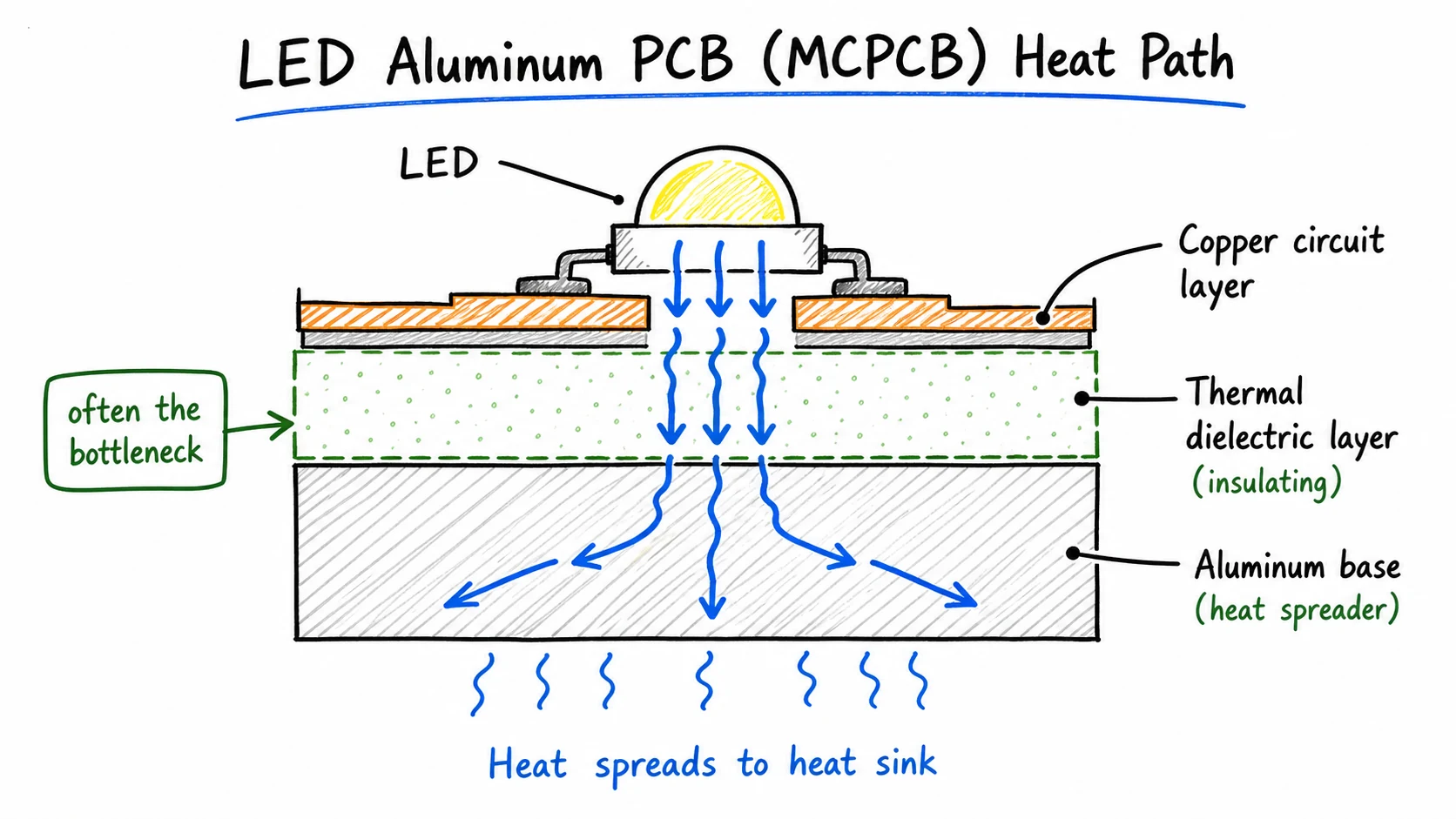 The thermal dielectric layer is often the bottleneck in an LED aluminum PCB heat path.
The dielectric layer is the key tradeoff. It must be thin and thermally conductive enough to move heat, but it must also maintain electrical insulation between the copper circuit and aluminum base.
For many standard LED lighting projects, a dielectric thermal conductivity around 0.6 to 0.8 W/mK (or 1.0 W/mK commercial grade) is a practical starting range. Higher ratings, such as 2.0 W/mK or above, can help when power density is high, the heatsink path is constrained, or junction temperature control is especially strict.
But higher thermal conductivity is not automatically better for every product. If the LED power level and housing design do not require it, over-specifying a high-conductivity dielectric can increase board cost without a measurable improvement in the finished lamp.
For applications beyond the practical limits of aluminum CCL, such as very high-power chips or harsh thermal environments, ceramic PCB may be worth evaluating.
6 Critical CCL Specifications Every Sourcing Manager Should Compare
Before sending an RFQ, compare the specifications that actually affect production, reliability, and cost.
1. Copper Weight
Copper weight is usually specified in ounces per square foot or in micrometers. Common values are 0.5 oz, 1 oz, and 2 oz, roughly 17 um, 35 um, and 70 um.
For LED lighting boards, copper thickness affects current capacity, heat spreading in the copper layer, etching precision, and cost. Heavier copper can help with current and heat spreading, but it also increases material use and may limit fine trace geometry.
2. Dielectric Thickness
For aluminum PCBs, the dielectric is the insulating layer between the copper circuit and the aluminum base.
Thinner dielectrics reduce thermal resistance, but they also reduce insulation margin. Thicker dielectrics improve insulation robustness but can make heat transfer harder. The right choice depends on operating voltage, insulation requirements, LED power, and the thermal design of the housing.
3. Thermal Conductivity
Thermal conductivity of the dielectric is measured in W/mK. For standard volume LED aluminum PCB projects, 0.6 to 0.8 W/mK is a practical baseline range (with 1.0 W/mK available for commercial specifications). Materials above 2.0 W/mK are available, but they usually cost more and should be selected only when the thermal budget justifies them.
Confirm the LED junction temperature target, copper layout, board thickness, and heatsink path before specifying thermal conductivity.
4. Dielectric Breakdown Voltage
Breakdown voltage describes how much electrical potential the dielectric can withstand before insulation failure.
For mains-connected LED products, this is safety-critical. Requirements can vary by product type, insulation class, certification target, and local market. Many projects specify breakdown or hipot requirements in the 1,000 V AC to 3,000 V AC range, but the correct value should come from the product safety design and certification plan, not from a generic blog article.
5. Tg and CTE
Tg, or glass transition temperature, describes when the resin matrix begins to soften. CTE, or coefficient of thermal expansion, describes how much the material expands and contracts with temperature.
For SMT assembly and field use, mismatched expansion between the PCB, solder joints, and LED components can contribute to solder fatigue. Tg and CTE should be checked when the board will see high reflow temperatures, thermal cycling, or demanding operating environments.
6. Flame Rating
UL 94 V-0 is a common flammability rating requested for many PCB base materials used in consumer and commercial products. Many common aluminum PCB materials are available with V-0 rated systems, but buyers should still confirm the rating on the material datasheet and match it to the finished product compliance requirements.
| Specification | Unit | Practical LED PCB Range | Sourcing Action |
|---|---|---|---|
| Copper weight | oz or um | 0.5 oz to 2 oz is common | Confirm current and trace width requirements |
| Dielectric thickness | um | Often around 75 to 150 um for LED boards | Balance heat transfer and insulation margin |
| Thermal conductivity | W/mK | 0.6 to 0.8 W/mK baseline (1.0 W/mK commercial) for standard LED projects | Avoid over-specifying beyond actual heat load |
| Breakdown voltage | V AC | Often specified by product safety target | Confirm from certification and insulation requirements |
| Tg | deg C | Common or high-Tg grades depending on assembly and use | Match to reflow profile and field conditions |
| Flame rating | UL 94 | V-0 is often requested | Confirm on material datasheet |
Understanding Copper Clad Laminate Cost and Pricing Factors
Laminate pricing is not a flat commodity number. If quotes are higher than expected, the reason often sits inside the material specification.
Material family is a major cost driver. Standard FR-4 is usually the most economical rigid laminate. Aluminum IMS adds cost because of the metal base and specialized dielectric. Copper-backed IMS and specialty high-performance laminates cost more again.
Copper weight affects both material and processing cost. Thicker copper uses more raw copper and may require longer etching time or wider design rules. Moving from 1 oz to 2 oz copper can increase the board price, especially at volume.
Dielectric performance also affects cost. Higher thermal conductivity materials often use ceramic-filled or specialty resin systems. If a 0.6–0.8 W/mK baseline (or 1.0 W/mK commercial) material is enough for your LED module, specifying 2.0 W/mK or higher can add cost without solving a real problem.
Panel utilization affects yield. A board outline that nests efficiently in the production panel wastes less material. Unusual shapes, narrow strips, and poor nesting can increase scrap and raise unit cost.
Material availability matters for repeat orders. Common stock materials are easier to reorder consistently. Niche brands or rare grades can create lead-time and price risk.
Small copper clad sheets sold on consumer electronics marketplaces are not useful price references for industrial PCB fabrication. Production pricing depends on the finished board specification, panel design, quantity, lead time, and assembly scope. For a broader view, see aluminum PCB cost factors.
Sourcing Checklist: Preparing CCL Specifications for a PCB Quotation
When you request an aluminum PCB quote, you are not ordering raw laminate. You are specifying a finished PCB, and the factory chooses a laminate that matches the job.
Prepare the following before requesting a quote:
- Gerber files or fabrication drawings: Include copper layers, solder mask, silkscreen, drill map, and board outline.
- Substrate specification: State aluminum base thickness, copper thickness, and total finished board thickness.
- Thermal conductivity target: Give the required W/mK value, or describe LED power and ask for a practical recommendation.
- Dielectric breakdown or insulation requirement: Especially important for mains-connected LED products.
- Surface finish: Common choices include lead-free HASL, ENIG, and OSP. For LED lighting, white solder mask is often specified for light reflection.
- Solder mask color: White is common for LED boards, but confirm if the product needs another color.
- Order quantity and delivery requirement: Provide sample quantity, first batch size, and expected repeat volume.
- SMT assembly requirements: If you need assembly, include BOM, pick-and-place file, LED polarity notes, and testing requirements.
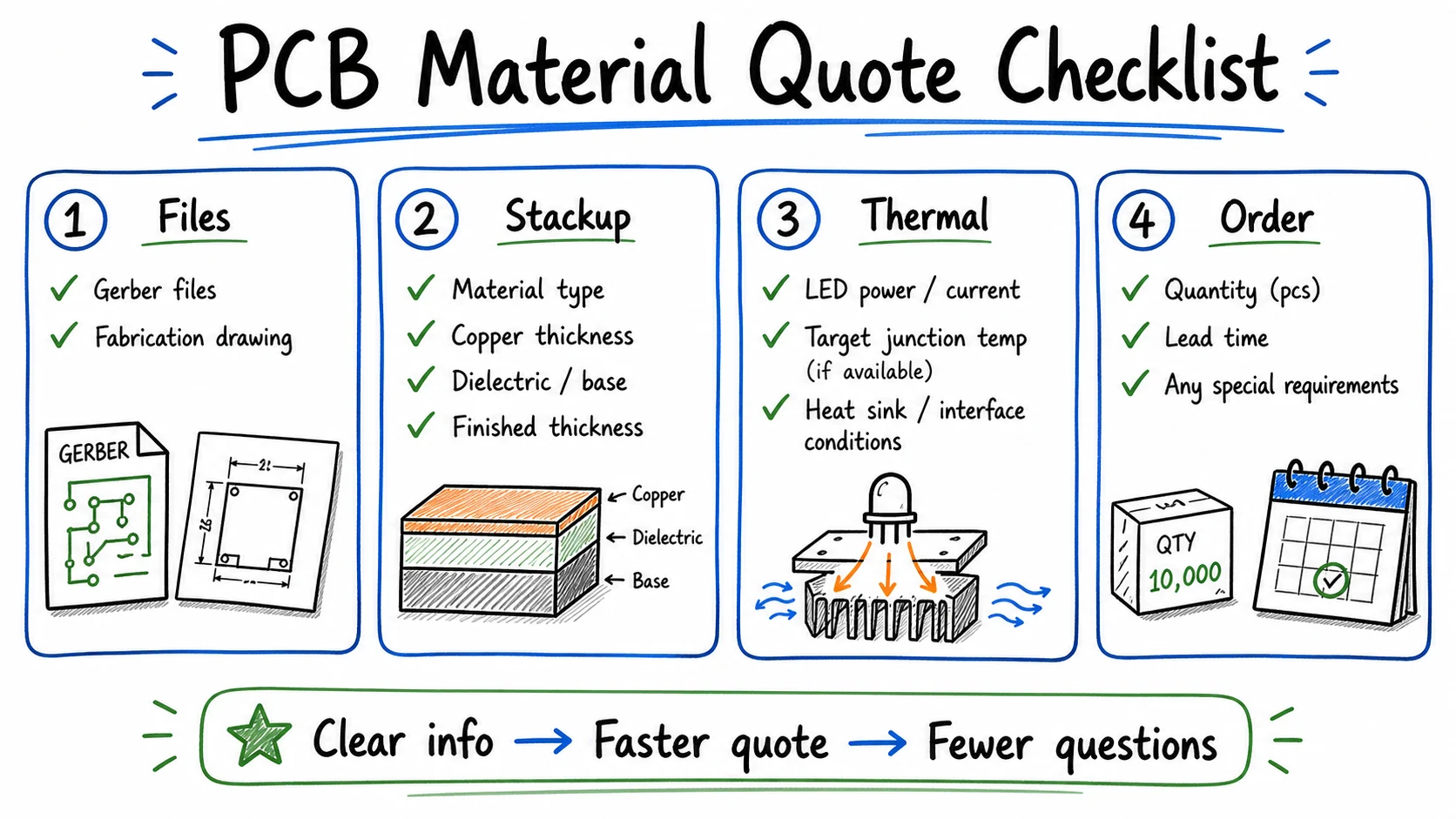 Clear PCB material and order information helps the factory quote CCL-related requirements faster and with fewer follow-up questions.
If you are not sure about the dielectric specification, discuss it with the factory before locking the design. Over-specifying a high thermal conductivity dielectric when a standard aluminum board is enough adds cost without improving the product.
For a quick start, contact aluminum PCB fabrication with your drawings and application information. If your project includes component sourcing and placement, see SMT assembly for full-package options.
Conclusion
Sourcing copper clad laminate for LED PCBs is a balance between heat, insulation, manufacturability, and unit cost.
For many standard indoor and commercial LED products, a practical aluminum PCB specification with 1 oz copper, white solder mask, and a 0.6 to 0.8 W/mK baseline (or 1.0 W/mK commercial) dielectric is a strong starting point. Higher specifications make sense when the heat load, insulation requirement, or certification target actually requires them.
If you are preparing an RFQ for LED PCBs, send us your Gerber files, board thickness, copper weight, thermal requirement, assembly needs, and target quantity.
Lumina PCB can review the layout and help you choose a practical base material for production, instead of paying for CCL specifications your product does not need.
Need a quotation?
Send Gerber files and basic specifications. We reply within 1 business day.
Ask for Quote