PCB Material Selection for LED Buyers: FR-4, Aluminum PCB, or Ceramic?

On This Page
PCB material usually means the materials that make up a printed circuit board:
- substrate
- copper
- solder mask
- silkscreen
But in buying conversations, most people use "PCB material" to mean the substrate — the base structure that defines what kind of board they need.
For standard electronics, FR-4 is the common starting point.
For LED lighting boards, aluminum PCB or MCPCB is often the better fit because the metal-backed structure helps move heat away from LEDs.
Ceramic PCB is usually reserved for cases where aluminum PCB cannot meet the thermal, insulation, CTE, or thermal-cycling target.
The right choice is not the material with the highest thermal conductivity on paper.
It is the board structure that actually fits the LED project's heat, reliability, cost, and production needs.
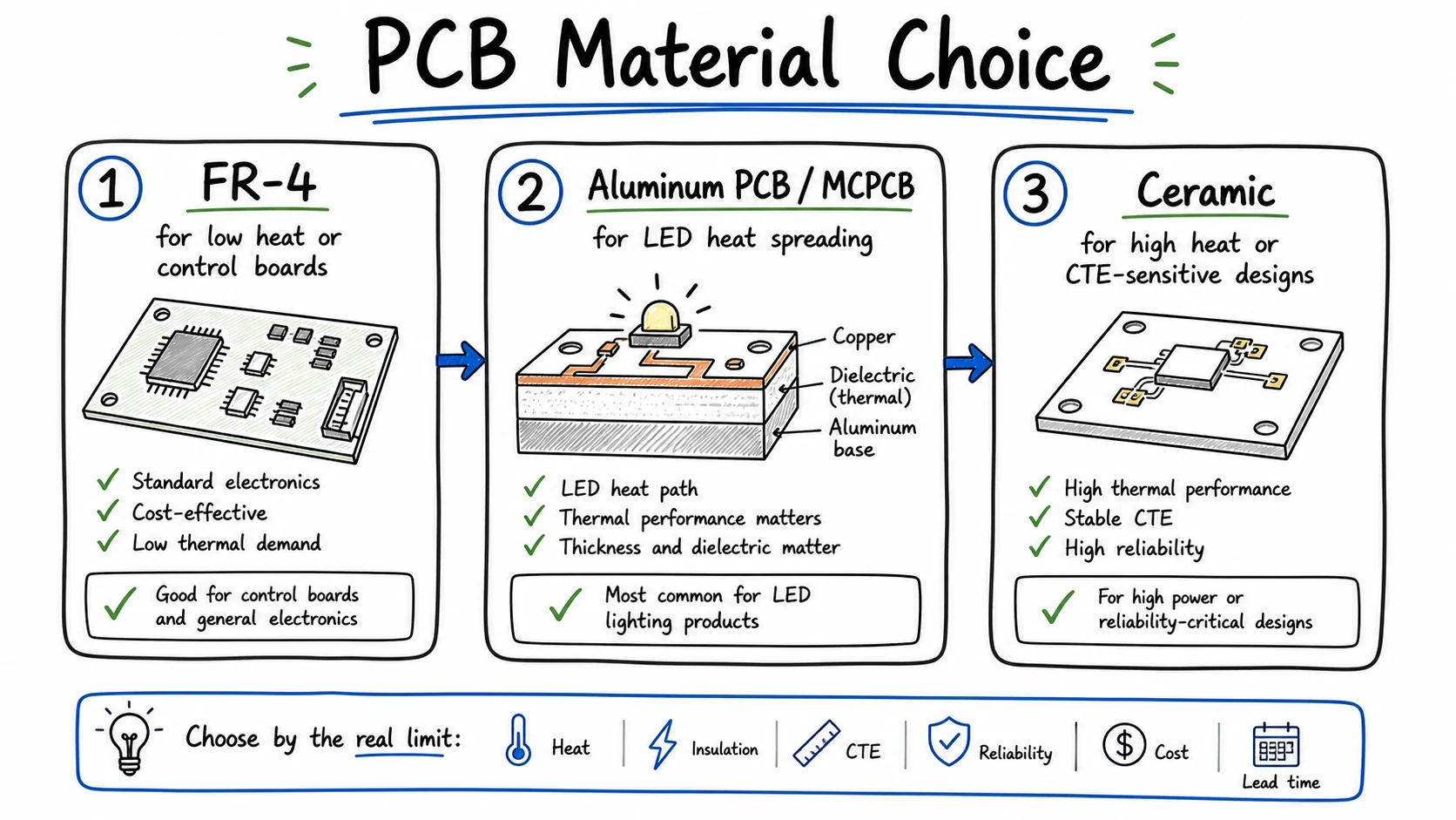 For LED boards, material choice should follow the real limit: heat, insulation, CTE, reliability, cost, or lead time.
What Does PCB Material Mean?
PCB material refers to the material stack that forms the board — substrate, copper, solder mask, and silkscreen. But a supplier cannot quote from that alone. They need to know what kind of board structure the project requires.
For example:
- FR-4 PCB
- aluminum PCB
- metal core PCB
- ceramic PCB
- polyimide flexible PCB
- high-frequency laminate PCB
Each one serves a different purpose and follows a different fabrication path.
For LED lighting buyers, the main decision usually comes down to three paths:
FR-4.
Aluminum PCB / MCPCB.
Ceramic.
The PCB Material Types Buyers Usually See
Most PCB material guides list a lot of options.
That is useful for research.
But not every material family matters equally for LED lighting.
Here is the buyer version:
| Material Type | Typical Use | LED Lighting Relevance | Buyer Caution |
|---|---|---|---|
| FR-4 | Standard electronics, control boards, low-cost PCBs | Useful when heat is low or not board-limited | Weak thermal path for higher-power LED boards |
| CEM / low-cost laminate | Low-cost consumer boards | Usually not the main choice for Lumina-style LED aluminum PCB work | Often chosen for cost, not thermal performance |
| Rogers / RF laminates | RF, microwave, high-frequency designs | Usually not needed for standard LED lighting | Do not specify unless the circuit really needs RF performance |
| Polyimide | Flex circuits and high-temperature flexible designs | Relevant mainly for flex or special assemblies | Different sourcing and process path |
| Aluminum PCB / MCPCB / IMS | LED lighting, power boards, heat-spreading designs | Very relevant for LED modules and luminaires | The dielectric layer must be chosen carefully |
| Ceramic PCB | High thermal density, CTE-sensitive, high-reliability designs | Relevant when MCPCB is no longer enough | Higher cost and more specialized processing |
This piece focuses on the three that matter most for LED boards:
FR-4, aluminum PCB, and ceramic.
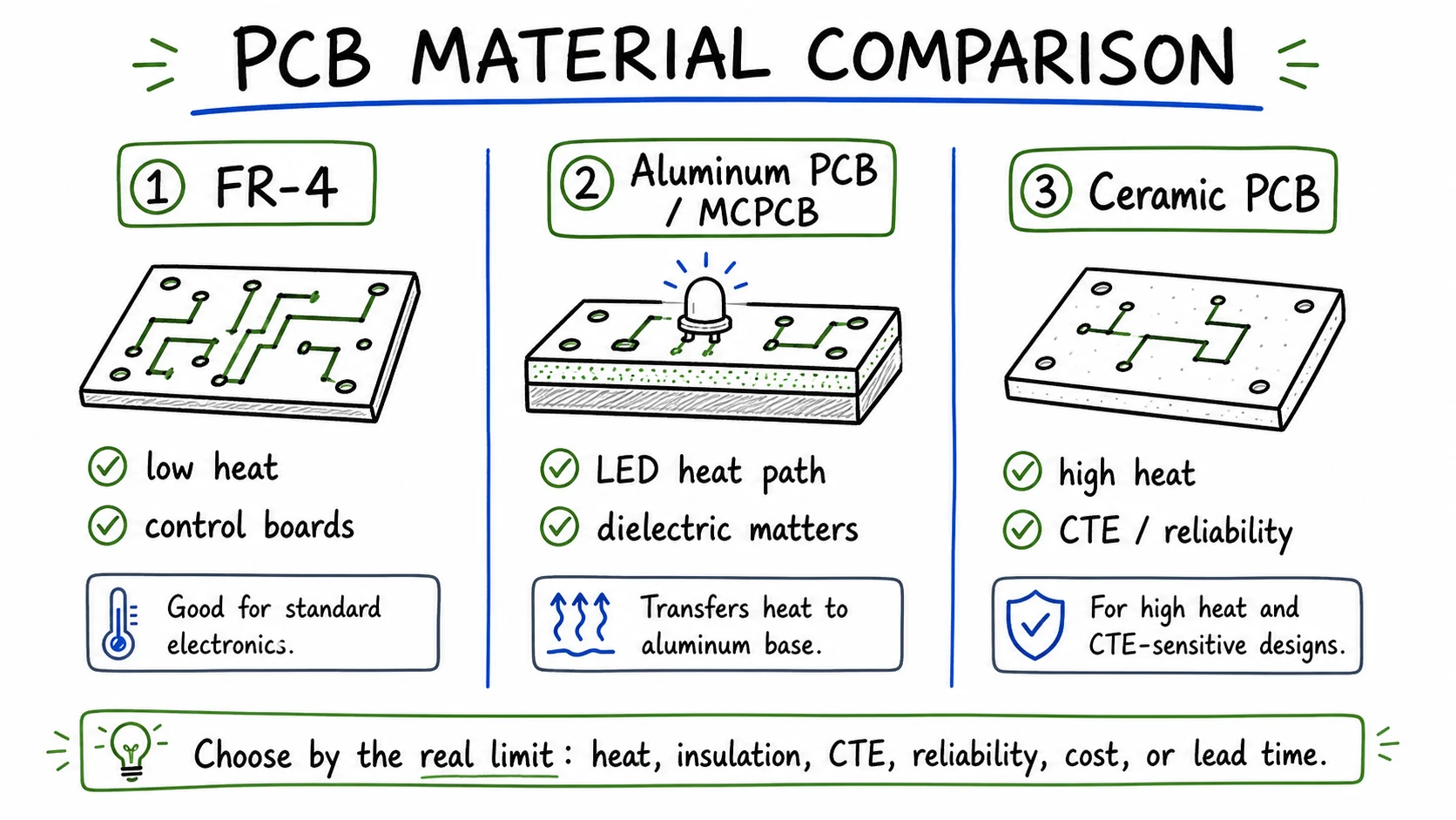 FR-4, aluminum PCB, and ceramic PCB solve different problems. The right choice depends on what the LED board needs the material to do.
FR-4: The Standard Choice When Heat Is Not the Main Problem
FR-4 is the default PCB material for most electronics — widely available, easy to fabricate, and good enough for many standard control circuits and low-cost boards.
But FR-4 is not a strong thermal material.
Typical FR-4 thermal conductivity sits around 0.25–0.5 W/mK, depending on the laminate grade.
That is enough for many electronic products.
It is not enough for many LED boards where the PCB is part of the heat path.
For a higher-performance FR-4 family example, see Isola FR408HR.
FR-4 can still be acceptable when:
- LED power is low
- heat is spread over a large area
- the board is mainly a control PCB
- the LEDs are not thermally limited by the board
- the product has another effective thermal path
So the mistake is not using FR-4.
The mistake is using FR-4 when the board itself needs to carry heat away from LEDs.
For most LED lighting products, aluminum PCB is the next step up.
Aluminum PCB / MCPCB: The Usual LED Thermal Structure
An aluminum PCB is often called an MCPCB or IMS board in buying conversations.
The structure is different from FR-4.
A common aluminum PCB stackup looks like this:
- solder mask
- copper circuit layer
- thermally conductive dielectric layer
- aluminum base
The copper carries current and spreads some heat.
The dielectric layer provides electrical insulation and transfers heat.
The aluminum base spreads heat toward the fixture body or heat sink.
This is why aluminum PCB dominates LED lighting.
You get a much stronger thermal path than FR-4 — without the cost and complexity of ceramic.
But there is one detail you should not miss:
The dielectric layer is often the bottleneck.
The aluminum base can spread heat well.
But heat still has to pass through the insulating dielectric layer before it reaches the aluminum.
That layer creates a real tradeoff. A thinner dielectric lowers thermal resistance, but it also reduces your insulation margin — useful when heat is the dominant limit and voltage demand is manageable. A thicker dielectric improves isolation and safety margin, but blocks more heat. Higher-performance dielectric materials can improve the thermal path at a given thickness, though you should check actual datasheet values rather than marketing claims.
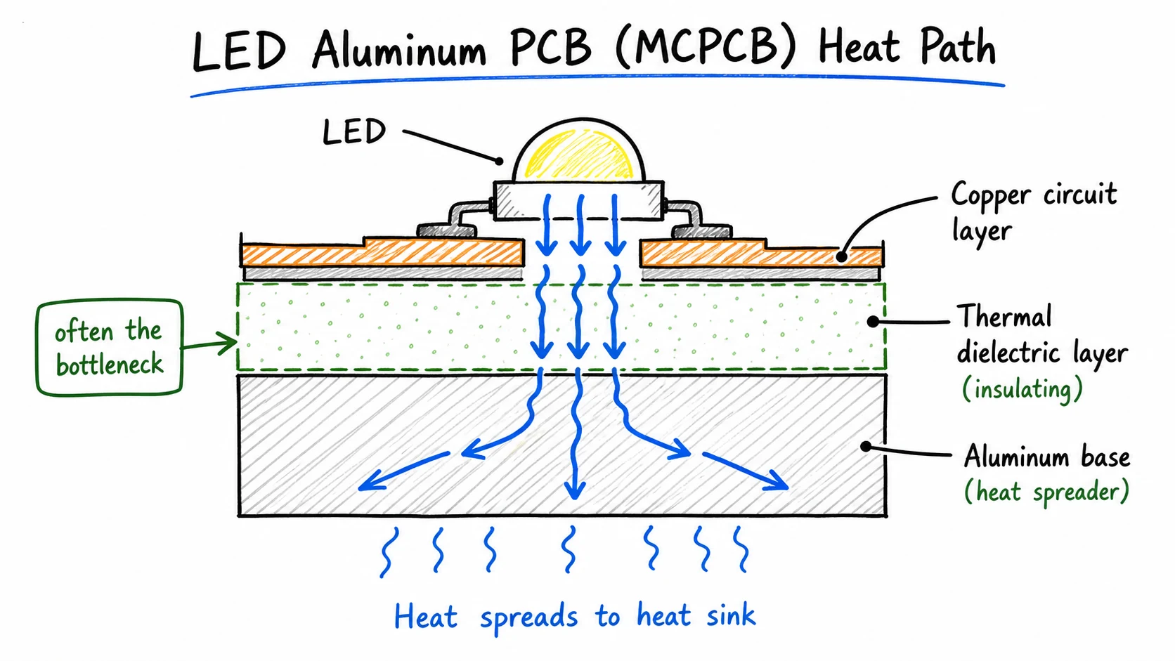 In an aluminum PCB, heat still has to pass through the insulating dielectric layer before it reaches the aluminum base.
Common LED MCPCB dielectric thickness bands include 38 um, 50 um, 75 um, and 100 um.
But thinner is not automatically better.
A practical rule: use the thinnest dielectric that still meets the insulation and safety requirement, without pushing thermal resistance beyond what the LED system needs.
Supplier datasheets matter here.
Laird's Tlam thermally conductive PCB system frames IMS materials around thermal performance and dielectric strength, which is why dielectric thickness cannot be chosen from thermal conductivity alone.
So do not just ask for "high thermal conductivity." Ask what dielectric thickness, thermal conductivity grade, and isolation voltage the board actually needs.
For most LED lighting projects, getting the MCPCB dielectric specification right matters more than chasing the highest-rated material on the market.
If you are preparing an LED aluminum PCB project, Lumina's aluminum PCB fabrication page is a better next step than a general PCB material list.
Ceramic PCB: When Aluminum PCB Is No Longer Enough
Ceramic PCB can be useful.
But it is not the automatic upgrade.
Ceramic starts to make sense when the substrate itself has to support the thermal and reliability target.
That can happen when:
- power density is very high
- the LED attach area is small
- thermal cycling is severe
- CTE mismatch is stressing the package or solder joints
- the MCPCB dielectric layer is the real thermal limit
- the project values reliability more than cost reduction
The two ceramic materials you will usually encounter are alumina and aluminum nitride. Alumina (Al₂O₃) sits around 24–27 W/mK for 96% purity grades, with a CTE of roughly 6.5–8 ppm/°C — a solid step up from organic laminates when insulation and dimensional stability matter. Aluminum nitride (AlN) is the higher-performance option, typically 170–220 W/mK and a CTE closer to 4.2–5.8 ppm/°C, which makes it useful when heat removal and CTE matching to chip materials are both critical. CeramTec's substrate pages for alumina and AlN are good references for how these materials are positioned in practice.
Those are typical ranges, not universal promises.
Actual values depend on material grade, supplier, purity, thickness, metallization, and test method.
Kyocera's CTE matching guidance is a useful reference for why thermal expansion mismatch matters in reliability-sensitive assemblies.
Ceramic also does not use Tg in the same way as FR-4 because it is not a polymer laminate.
That is one reason ceramic behaves differently in high-temperature environments.
But ceramic brings trade-offs:
- higher material cost
- more specialized supplier base
- different design rules
- more handling risk
- possible chipping or cracking
- longer sourcing path
So the question is not:
"Is ceramic better?"
The better question is:
"What limit can aluminum PCB not solve?"
If there is no clear answer, ceramic may only add cost and process risk.
For a deeper comparison, see Lumina's guide to ceramic PCB vs aluminum PCB.
Key PCB Material Properties Buyers Should Check
Here are the properties that come up in most LED board conversations:
| Property | What It Means | Why It Matters for LED Boards | What to Ask |
|---|---|---|---|
| Thermal conductivity | How well a material conducts heat | Helps compare FR-4, IMS dielectric, alumina, and AlN | What is the material grade and test value? |
| Thermal resistance | How much the full path resists heat flow | Depends on thickness, area, copper, dielectric, interface, and heat sink | Where is the real bottleneck? |
| Tg | Glass transition temperature for polymer laminates | Helps with assembly survivability and high-temperature stability | Is standard Tg enough, or is high-Tg needed? |
| CTE | How much the material expands with temperature | Affects solder joints, vias, and thermal-cycling reliability | Is CTE mismatch a reliability concern? |
| Dielectric strength | Insulation capability | Important for isolation and safety margin | What voltage withstand is required? |
| Moisture absorption | How much moisture the material absorbs | Can affect assembly and long-term reliability | Does the material need baking or special handling? |
| Cost and availability | Sourcing and production reality | Affects lead time and repeat orders | Is the material stocked and repeatable? |
Tg and CTE are worth separating.
Tg is mostly an assembly and heat-stability issue.
If a laminate gets close to or above Tg, stiffness drops and expansion can increase.
That can lead to warpage, delamination, or soldering problems.
CTE is more about long-term thermal cycling.
If the board, solder, package, and chip expand at different rates, repeated heating and cooling can create mechanical stress.
That can lead to solder fatigue, cracks, lifted pads, or interface separation.
Cree LED's PCB thermal performance note is a useful reminder that board-level thermal design depends on the full heat path, not only on the substrate name.
For LED boards, check both — but focus on Tg during assembly planning and CTE during reliability evaluation.
How to Choose PCB Material for LED Lighting
Start with the LED's heat and reliability target — not the material name.
Most bad material decisions happen because someone picks a substrate first and checks the thermal math later.
A practical way to think about it:
| Buyer Situation | Better Starting Point | Why | What to Confirm |
|---|---|---|---|
| Low-power LED or control circuit | FR-4 | Heat is not board-limited | Temperature rise and layout margin |
| Standard LED lighting board | Aluminum PCB / MCPCB | Better heat path with controllable cost | Dielectric, copper, base thickness, finish |
| Compact high-output module | Aluminum PCB review first; ceramic if needed | Heat flux may expose the dielectric bottleneck | Junction temperature and heat sink path |
| Severe thermal cycling or package stress | Ceramic may be justified | CTE and solder reliability may dominate | Package, substrate, and cycling requirement |
| High-reliability thermal-critical module | Alumina or AlN review | Material choice may be part of reliability design | Thermal, insulation, CTE, and supplier capability |
Before moving from one material class to another, ask four questions:
- What is the LED junction-temperature target?
- What is the actual heat flux per board area?
- Where is the real bottleneck: substrate, dielectric, copper, interface, heat sink, or enclosure?
- Does CTE mismatch or thermal cycling justify ceramic instead of MCPCB?
If the answer is "moderate heat, manageable temperature rise, and no severe cycling," then aluminum PCB may be enough.
If even a suitable MCPCB stackup cannot meet the target, ceramic becomes worth reviewing.
And if the circuit is low-power and heat is not a real limit, FR-4 may still be fine.
Material choice should follow the constraint.
Not the other way around.
Common Material Selection Mistakes
The most common mistake is overbuying thermal performance the LED system will not use.
A higher-k material does not help much if the real bottleneck is somewhere else.
For example:
- LEDs are packed too closely
- copper spreading is poor
- the thermal interface material is weak
- the board does not contact the heat sink well
- the fixture body traps heat
- the operating current is too high for the mechanical design
In those cases, changing the PCB material may not fix the product.
Here are the mistakes worth avoiding:
| Mistake | Why It Causes Problems | Better Question |
|---|---|---|
| Choosing by material name | The name does not define the full stackup | What target must the board meet? |
| Asking for the highest thermal conductivity | The real limit may be thickness, interface, or heat sink path | Where is the thermal bottleneck? |
| Choosing ceramic too early | Cost and sourcing burden can rise without real benefit | Has MCPCB actually failed the target? |
| Assuming FR-4 is always wrong | Some LED or control boards do not need MCPCB | Is heat really board-limited? |
| Ignoring lead time | Special materials can narrow supplier options | Can this material support repeat production? |
One rule of thumb saves a lot of trouble: the right material is the one that meets the requirement without adding unnecessary cost, sourcing risk, or process complexity.
What to Send Before Asking for a PCB Material Quote
Do not send only a material name.
"FR-4 PCB."
"Aluminum PCB."
"Ceramic PCB."
Those labels are a starting point.
They are not a quote package.
For a useful review, send:
| Item | Needed For | Why It Matters |
|---|---|---|
| Gerber files | Bare board fabrication | Defines copper, solder mask, drill, outline, and board features |
| Fabrication drawing | Manufacturing review | Shows size, thickness, tolerances, finish, slots, and notes |
| Board size and thickness | Material and cost check | Affects panel use, material choice, and handling |
| Copper thickness | Current and thermal spreading | Affects performance and quote |
| Surface finish | Solderability and shelf life | OSP, HASL, ENIG, and other finishes affect cost and process |
| Solder mask / silkscreen requirement | Production and appearance | Color and marking requirements may affect quote |
| Dielectric thermal conductivity | Aluminum PCB review | Helps check the heat path |
| Dielectric thickness | Aluminum PCB review | Balances heat transfer and insulation |
| Aluminum base thickness | Aluminum PCB review | Affects mechanical and heat-spreading structure |
| Isolation voltage | Safety / electrical requirement | Prevents under-specifying dielectric performance |
| LED power/current | Thermal review | Helps estimate heat load |
| Heat sink or housing details | System thermal path | PCB material cannot solve a poor fixture path alone |
| BOM and pick-and-place | SMT assembly | Needed if assembled LED boards are required |
| Quantity and lead time | Production planning | Affects price, scheduling, and material availability |
If the project needs bare boards only, the fabrication files and material notes may be enough.
If the project needs assembled LED boards, include BOM, pick-and-place, assembly drawing, and test requirements.
For assembled LED aluminum PCB projects, see Lumina's SMT assembly for LED aluminum PCB.
For bare aluminum boards, start with aluminum PCB fabrication.
Before You Choose the Material
The wrong way to start: pick a material name, then check if it works.
The better way: define what the LED board needs to survive — heat, cycling, insulation, cost pressure — and let that narrow the material.
Low heat and tight budget? FR-4 may be enough.
Standard LED thermal board? Aluminum PCB / MCPCB handles most cases.
High heat flux, CTE stress, or strict reliability? Ceramic enters the conversation.
Need help narrowing it down?
Send your drawing, Gerber files, LED power and current, quantity, and assembly requirements. Lumina can review whether FR-4, aluminum PCB / MCPCB, or ceramic fits the project.
Join Our Industrial Community
Get exclusive technical whitepapers and industry news delivered to your inbox every month. No spam, only professional insights.