SMT Line: A B2B Guide to LED Aluminum PCB Assembly

On This Page
SMT Line: A B2B Guide to LED Aluminum PCB Assembly
An SMT line is a sequence of automated machines used to print solder paste, place components, reflow solder joints, and inspect assembled boards. In a typical production flow, each board moves through the required SMT steps before shipment.
For LED aluminum PCBs, the process is more demanding than standard FR-4 assembly. The metal base absorbs heat differently, and poor thermal pad soldering can reduce the finished board's heat dissipation path.
Most suppliers will tell you they have an SMT line. Fewer will explain whether the process is suitable for metal-core boards, or which inspection and testing steps are actually used for your order.
This guide explains the SMT line process and the files buyers should prepare before asking for a quote.
What Is an SMT Line in Electronics Manufacturing?
An SMT line mounts components directly onto a PCB surface, without inserting component leads through drilled holes.
SMT means Surface Mount Technology. It is the assembly method. SMD means Surface Mount Device, which refers to components such as LEDs, resistors, capacitors, and ICs designed to sit on the board surface.
The line is a physical chain of machines. Solder paste goes on first. Then components are placed. Then the board goes through a thermal oven. Then inspection and testing steps confirm whether the assembly meets the project requirements.
In LED lighting, SMT is the standard assembly method. LED packages are commonly designed as SMD parts so they can be placed automatically on aluminum boards at volume.
Note on terminology: Outside electronics manufacturing, "SMT" can mean CPU simultaneous multithreading or a financial trading term. In PCB assembly, it means Surface Mount Technology.
SMT Line vs. SMT Production Line vs. SMT Assembly Line: What Is the Difference?
In most supplier conversations, these three terms point to the same core idea. The wording varies by supplier and region.
- SMT production line tends to emphasize factory floor setup and throughput capacity.
- SMT assembly line tends to emphasize the PCBA service delivered to the buyer.
A fully automated line and a semi-automatic line can both be called "SMT lines." They may differ in lead time, placement accuracy, labor involvement, and solder joint consistency.
When evaluating a supplier, ask for the process flow, inspection checkpoints, and testing scope. The name used for the line tells you much less than the controls used during production.
The Step-by-Step SMT Line Process Flow
The SMT line runs in a fixed sequence. Each step prepares the board for the next one.
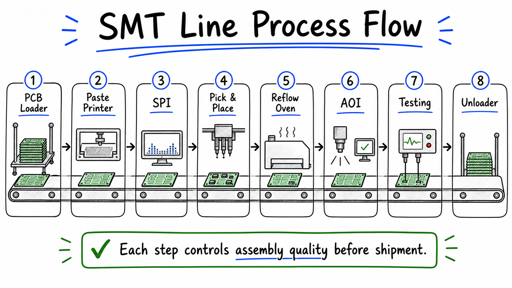 A typical SMT line moves each board through paste printing, SPI, placement, reflow, AOI, testing, and unloading.
Incoming Material Check
Before loading, the factory verifies boards, stencils, solder paste, and components. Problems at this stage can cause first-article failures later.
Solder Paste Printing
A stainless-steel stencil deposits paste onto the copper pads. Paste volume and position variation at this stage can create downstream defects, so printing is one of the most important process windows.
SPI, or Solder Paste Inspection
SPI measures paste height, volume, and alignment after printing. Catching paste problems before placement is usually easier and cheaper than finding them after reflow.
Component Placement
A pick-and-place machine reads optical targets and positions LEDs and passive parts from reels. Accuracy here affects solder joint quality and LED orientation.
Reflow Soldering
The board passes through a multi-zone thermal oven. The heating profile melts the solder paste and forms the electrical and mechanical solder joints. Controlled cooling helps reduce thermal stress.
AOI, or Post-Reflow Inspection
Cameras scan the board for visible defects such as missing parts, polarity errors, solder bridges, and tombstoned components. See AOI inspection in SMT assembly.
Testing
Electrical or functional tests confirm whether the assembled board meets the project requirements before it leaves the line.
For single-sided aluminum PCBs, the board usually goes through the SMT line once. Metal-core boards are heavier and conduct heat differently than FR-4, so conveyor support, fixture setup, and reflow profiling should be reviewed for the project.
SMT Line Equipment: What Each Machine Does
Knowing what each machine does makes it easier to ask the right questions when a supplier shares an equipment list.
| Machine | Core Function | Why Buyers Should Care |
|---|---|---|
| Stencil printer | Deposits solder paste through a metal stencil | Paste consistency strongly affects solder joint quality |
| SPI machine | Measures solder paste deposits in 3D | Helps catch printing problems before components are placed |
| Pick-and-place machine | Places components using optical alignment | Calibration and nozzle condition affect LED alignment and polarity accuracy |
| Reflow oven | Melts and solidifies solder through controlled thermal zones | Profile control is especially important for aluminum PCBs |
| AOI system | Uses cameras to inspect visible post-reflow defects | Finds surface defects, but cannot see hidden solder joints |
| X-ray / AXI system | Images hidden solder joints | May be used when void percentage or hidden solder joints must be verified |
| ICT / FCT station | Performs electrical or functional testing | Confirms whether the PCBA meets electrical or operating requirements |
Machine brand names can matter, but process control matters more. Calibration, maintenance, programming, and inspection feedback are what keep repeat orders stable.
SPI, AOI, X-ray, ICT, and FCT: Understanding the Quality Gates
Having an SMT line is not the same as having complete quality control. What matters is which gates are used for your order and whether the results feed back into production decisions.
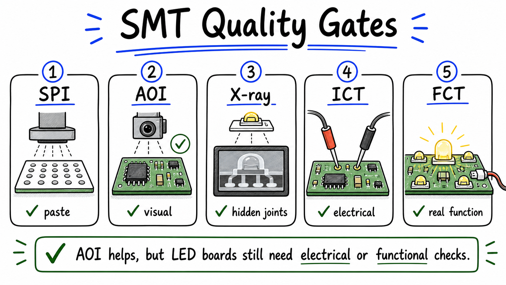 Different SMT quality gates catch different problems; LED boards still need electrical or functional checks after visual inspection.
| Quality Gate | Type of Check | Main Defects Detected | Why It Matters for LEDs |
|---|---|---|---|
| SPI | 3D paste measurement | Under-paste, over-paste, positional offset | Helps catch the root cause of many SMT defects before placement |
| AOI | Camera-based visual inspection | Missing parts, polarity errors, bridges, tombstoning | Fast visual check, but it cannot see hidden joints under components |
| X-ray / AXI | Internal imaging | Solder voids or hidden-joint issues | Useful when thermal pad solder coverage must be verified |
| ICT | Electrical continuity or circuit check | Opens, shorts, incorrect values depending on fixture coverage | Confirms circuit connectivity before functional testing |
| FCT | Functional verification | Operating behavior such as LED output, voltage, or current | Confirms whether the board works under defined conditions |
For LED boards, AOI alone is not enough. A board can look correct under a camera but still fail electrical or lighting requirements. Depending on the project, FCT or a point-lighting test may be used to confirm actual operation.
Many commercial PCBA projects use IPC-A-610 Class 2 workmanship standards as a practical baseline, but the required acceptance class should come from the customer's drawing, purchase documents, or application requirements.
Ask your supplier which gates run on every production order and which are project-specific or cost-extra. That answer tells you more than the equipment list.
LED Aluminum PCB SMT Assembly: What Makes It Different from FR-4?
Assembling on aluminum is not the same as assembling on FR-4. The metal core changes how the board responds in the reflow oven, and thermal pad soldering affects how well the board handles heat in use.
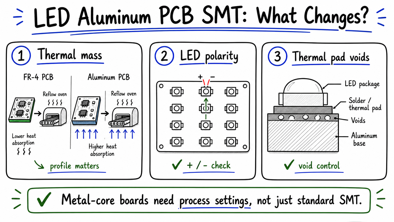 LED aluminum PCBs need process settings for metal-core thermal behavior, LED polarity, and thermal pad void control.
High Thermal Mass Reflow Profiling
The aluminum base draws heat differently than FR-4. A standard FR-4 profile may not be suitable for every aluminum PCB. The profile should bring the board to temperature without creating excessive thermal stress or warpage.
LED Polarity and Orientation
Dense LED arrays often use many identical-looking LEDs. One reversed LED can fail a lighting segment. Correct mounter programming and visual polarity checks should work together.
Thermal Pad Voiding Control
Many LED packages have a thermal pad underneath. Solder voids under this pad can reduce the heat path from the LED to the aluminum base. Stencil aperture design and reflow control can help reduce void risk.
Surface Finish
ENIG and OSP are often preferred for flatter SMT surfaces on LED aluminum PCBs. HASL may create more surface variation, so surface finish should be confirmed based on component package, soldering process, and project requirements.
Board Flatness and Support
Large aluminum panels can bow under heat. Fixtures, conveyor support, or process setup may be needed for stable handling.
For fabrication specifications, see aluminum PCB fabrication for LED lighting.
Buyer-Facing Cost Factors in SMT Assembly
SMT assembly quotes are driven by complexity, documentation, sourcing scope, test scope, and volume. Buyers do not need to focus on the factory's machine purchase price; they need to understand the variables that affect their own assembly quote.
Component Count and Density
More placement points mean more machine time, more programming, and more inspection. A 200-LED panel takes more setup and placement time than a 20-LED board, even at the same physical size.
Component Package Size
Common LED packages such as 3528, 5050, and 2835 are familiar in lighting assembly. Very small passives or fine-pitch ICs may slow the line and add inspection overhead.
Single-Sided vs. Double-Sided SMT
Single-sided assembly is simpler and often more practical for LED aluminum PCBs. Double-sided assembly requires extra setup and reflow planning, and it may not fit many metal-core board structures.
Turnkey vs. Consignment BOM
Turnkey assembly means the supplier sources the components. Consignment means the buyer supplies parts. The better option depends on approved vendor lists, component availability, pricing, and project control requirements.
NRE and Setup Costs
Stencil fabrication and machine programming are fixed setup costs for a design. They are spread across the order quantity, so per-unit cost often changes significantly between sample builds and mass production.
For many LED aluminum PCB projects, single-sided SMT with clear BOM data and a practical production quantity is the most efficient starting point.
RFQ Checklist: What Files Do Buyers Need to Provide for SMT Quoting?
Missing documents are one of the most common reasons SMT assembly quotes get delayed. Before submitting an RFQ, check that these files are ready.
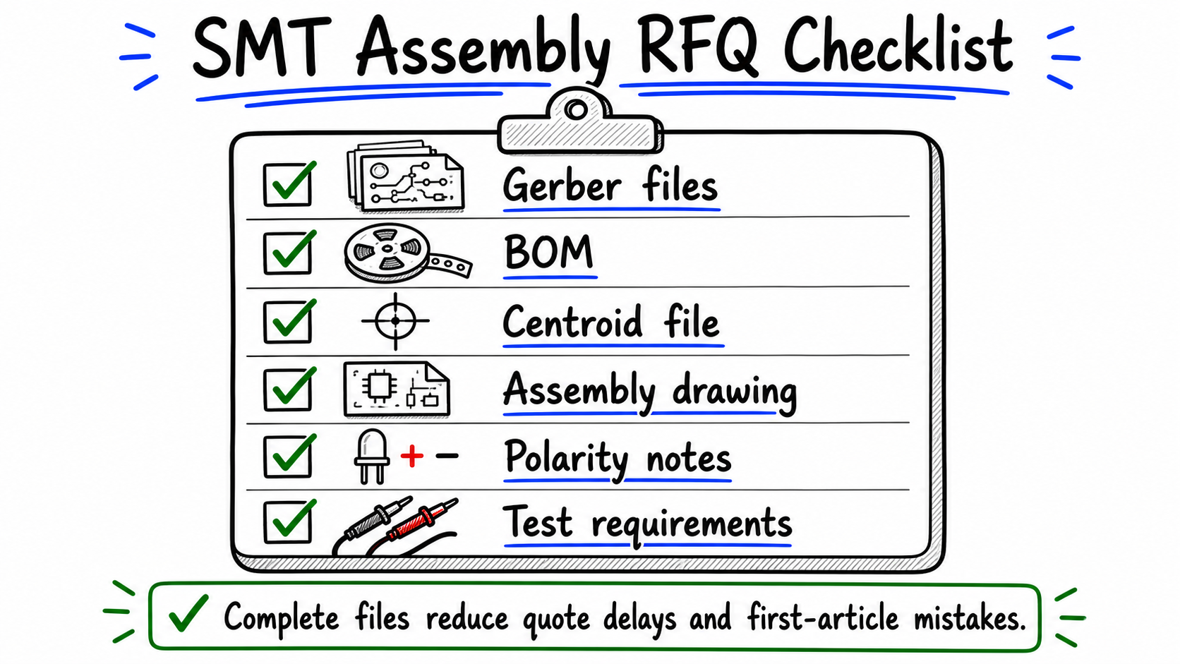 Complete SMT assembly files help the factory quote faster and reduce first-article mistakes.
Complete SMT Assembly RFQ Package:
- Gerber files, ODB++, or IPC-2581: Board outline, copper layers, solder mask, silkscreen, and paste data.
- Bill of Materials (BOM): Reference designators, manufacturer part numbers, quantities, package types, and acceptable substitutes if allowed.
- Centroid file, pick-and-place file, or CPL: X/Y coordinates, rotation angle, layer, and reference designator for each component.
- Assembly drawings: Component orientation, LED polarity marks, pin-1 indicators, connector directions, and special assembly notes.
- Test instructions: Input voltage, current limits, expected output, FCT criteria, marking, programming, or packaging requirements.
If anything is missing, the factory may need to ask for clarification before quoting. For a full breakdown of each file format, see PCB files for assembly.
For SMT assembly quotes, the engineering review should cross-reference the BOM, centroid data, paste layer, and assembly drawing. This helps catch footprint mismatches and LED orientation issues before they become production problems.
How Lumina Supports LED Aluminum PCB SMT Assembly
Lumina focuses on single-sided aluminum PCBs for LED lighting and supports coordinated PCB fabrication and SMT assembly for lighting projects.
Integrated Project Communication
Coordinating PCB fabrication and SMT assembly through one manufacturing partner can reduce handoff friction, shorten communication loops, and make technical clarification easier.
LED-Focused DFM Review
Before production, project files should be checked for paste layer consistency, thermal pad geometry, BOM-to-centroid matching, and LED orientation. These checks help reduce first-article risk.
Sourcing Flexibility
Depending on the project scope, buyers can discuss turnkey component sourcing or consigned components. Complete manufacturer part numbers and approved substitutes make this process smoother.
Sample-First Approach
A sample run before mass production can confirm the reflow profile, soldering result, orientation, and light output under real conditions. Problems found at sample stage are easier to correct than issues found after full production starts.
Learn more about SMT assembly for LED aluminum PCB.
Conclusion
For most LED lighting boards, SMT assembly comes down to three practical questions: is the reflow profile suitable for metal-core boards, is LED polarity controlled, and are the required inspection or functional checks defined before production?
When evaluating suppliers, ask directly: Can they support aluminum PCB assembly? Which inspection gates are used for this order? What files do you need before quoting?
Send us your Gerber files, BOM, centroid file, and SMT requirements. Our team will review the files and respond with a factory-direct quote covering LED aluminum PCB fabrication and SMT assembly.
Join Our Industrial Community
Get exclusive technical whitepapers and industry news delivered to your inbox every month. No spam, only professional insights.