How to Choose Aluminum PCB Copper Thickness for LED Lighting

On This Page (Table of Contents)
Copper thickness on an aluminum PCB is usually marked in oz or μm.
Many IMS material sheets and LED application notes talk about 0.5 oz (~18 μm), 1 oz (~35 μm), or 2 oz (~70 μm).
LED thermal notes such as onsemi AND9008 and IMS-oriented LED documentation often treat 35 μm (1 oz) as a standard copper thickness on metal-core boards, with thicker copper used when the design needs more current margin or heat spreading.
For many single-sided LED aluminum boards we produce in volume, 12 μm copper is a common production thickness.
Not because it is “more advanced.”
Because a lot of standard LED lighting layouts work with thinner copper when the drawing allows it.
Thicker copper helps current capacity and lateral heat spreading.
It does not automatically cool LEDs better.
Most of the heat still goes through the dielectric into the aluminum base.
For most quotes, copper thickness is already on the drawing or RFQ, and we produce to that specification.
If copper is not marked, confirm it before production.
What Aluminum PCB Copper Thickness Means (oz vs μm)
On a single-sided aluminum PCB, copper is the top circuit layer.
Under it sits the dielectric.
Under that sits the aluminum base.
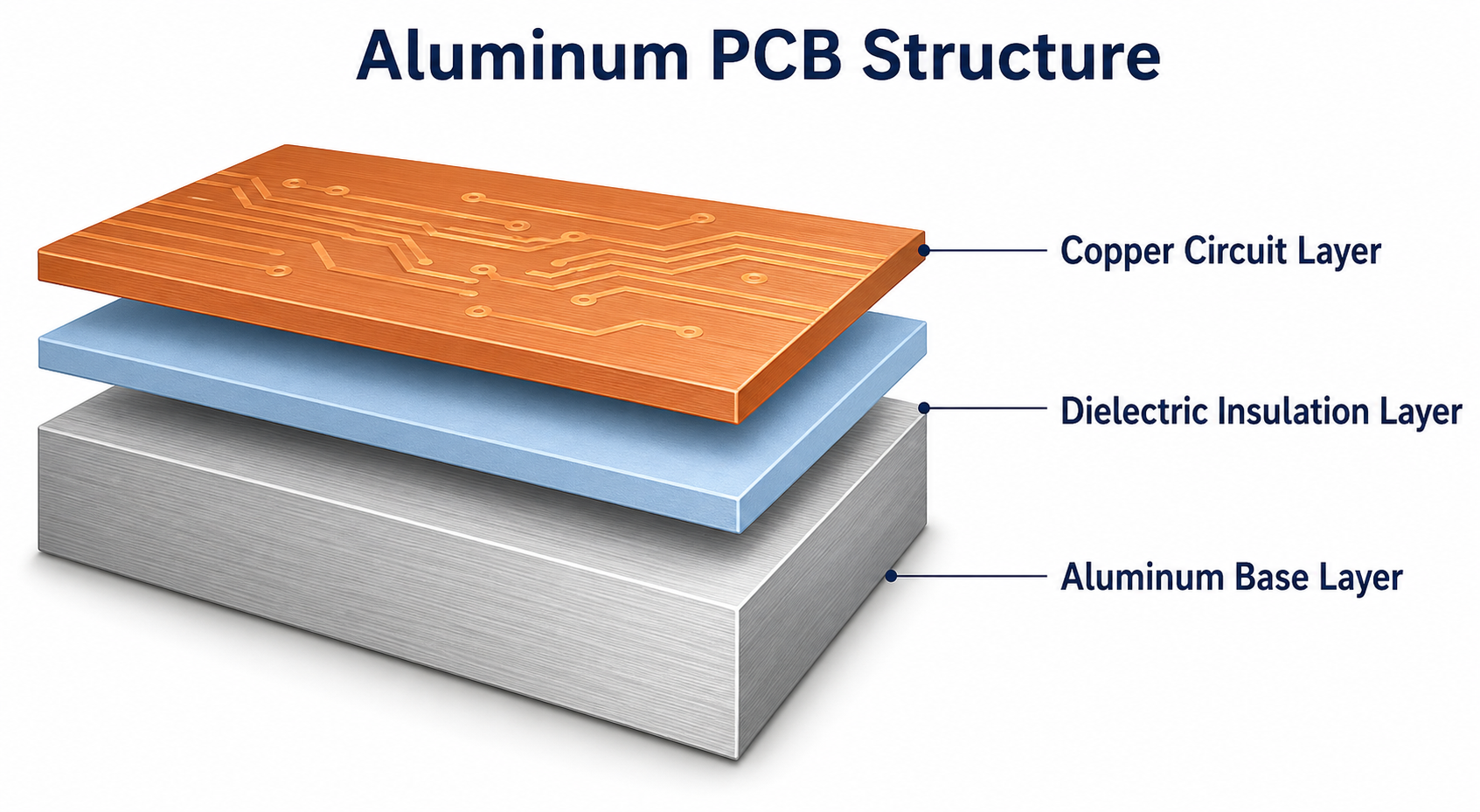 On a single-sided aluminum PCB, copper thickness is the top circuit layer—not the aluminum base thickness.
oz and μm are two ways to talk about the same copper foil.
They are not two different materials.
A common industry conversion treats 1 oz/ft² ≈ 35 μm and 0.5 oz ≈ 18 μm.
NCAB notes that copper weight is a nominal foil value, and finished copper after process can be lower than people expect from the oz label alone.
| Spec language | Approx. thickness | Notes |
|---|---|---|
| Common production thickness on many volume LED boards we build | ~12 μm | Roughly one-third ounce by orientation only |
| 0.5 oz | ~18 μm | Often near the lower end on IMS menus |
| 1 oz | ~35 μm | Common number in international LED / IMS notes |
| 2 oz | ~70 μm | Higher current or tighter layouts in the design |
| 3 oz | ~105 μm | Special builds, not routine lighting volume |
These are nominal values.
If your drawing needs a minimum finished copper thickness, write that clearly.
If not, the copper thickness on the drawing or RFQ is usually enough for quoting.
On our routine single-sided LED work, ~12 μm is the copper thickness we use most often.
Other thicknesses can be produced when the order requires them.
They are not the default for every board.
Why Datasheets Often Say 1 oz, While Many LED Boards Use 12 μm
Both can be true.
International IMS product data often list copper cladding from about 18 μm upward.
For example, Technoboards IMS documentation shows copper thickness ranges starting around 18 μm, not 12 μm.
Leiton’s aluminum / IMS design rules treat 35 μm as a standard copper thickness, with 70 μm and 105 μm as higher options.
LED-oriented notes also lean that way: standard IMS copper is often discussed at 35 μm, with 70 μm / 105 μm when the design needs more spreading or current margin.
In volume LED lighting production, many single-sided boards still use ~12 μm.
That is a common production choice for standard lighting panels, not a premium claim and not a global datasheet rule.
So the useful question is not “which document is wrong.”
It is:
What copper thickness is on your drawing, and is that what you want to buy?
| Source type | Typical copper discussed | How to use it |
|---|---|---|
| International IMS / LED app notes | 18 / 35 / 70 μm | Useful when reading overseas drawings and material menus |
| Volume LED aluminum boards (many standard lighting jobs) | ~12 μm common | Common production thickness when the drawing allows it |
| Capability menus | 0.5–10 oz listed | Options only, not a quality ranking |
Two common mistakes:
- Copy 1 oz or 2 oz from a capability page when the drawing does not need it.
- Keep thin copper on the quote, while the layout has very narrow power routes that the design never checked.
The first can raise cost without a clear gain.
The second is a design issue, not something a fabrication quote can “fix” by itself.
For aluminum PCB fabrication for LED lighting, we follow the copper thickness on the file or agreed specification.
If cost is a concern, thicker copper is one place buyers often over-spec. See also our notes on aluminum PCB cost.
Current Capacity: Trace Width and Copper Thickness Work Together
Current capacity is not decided by copper thickness alone.
IPC-2152 treats conductor sizing as a thermal problem: current, conductor width, copper thickness, board construction, and environment all affect temperature rise.
A companion technical summary of IPC-2152 makes the same point: thickness and width both matter, and there is no single universal amp rating for every board.
Think in cross-section:
width × thickness
Thinner copper means less copper in the path at the same width.
So the traces usually need to be wider if the current is the same.
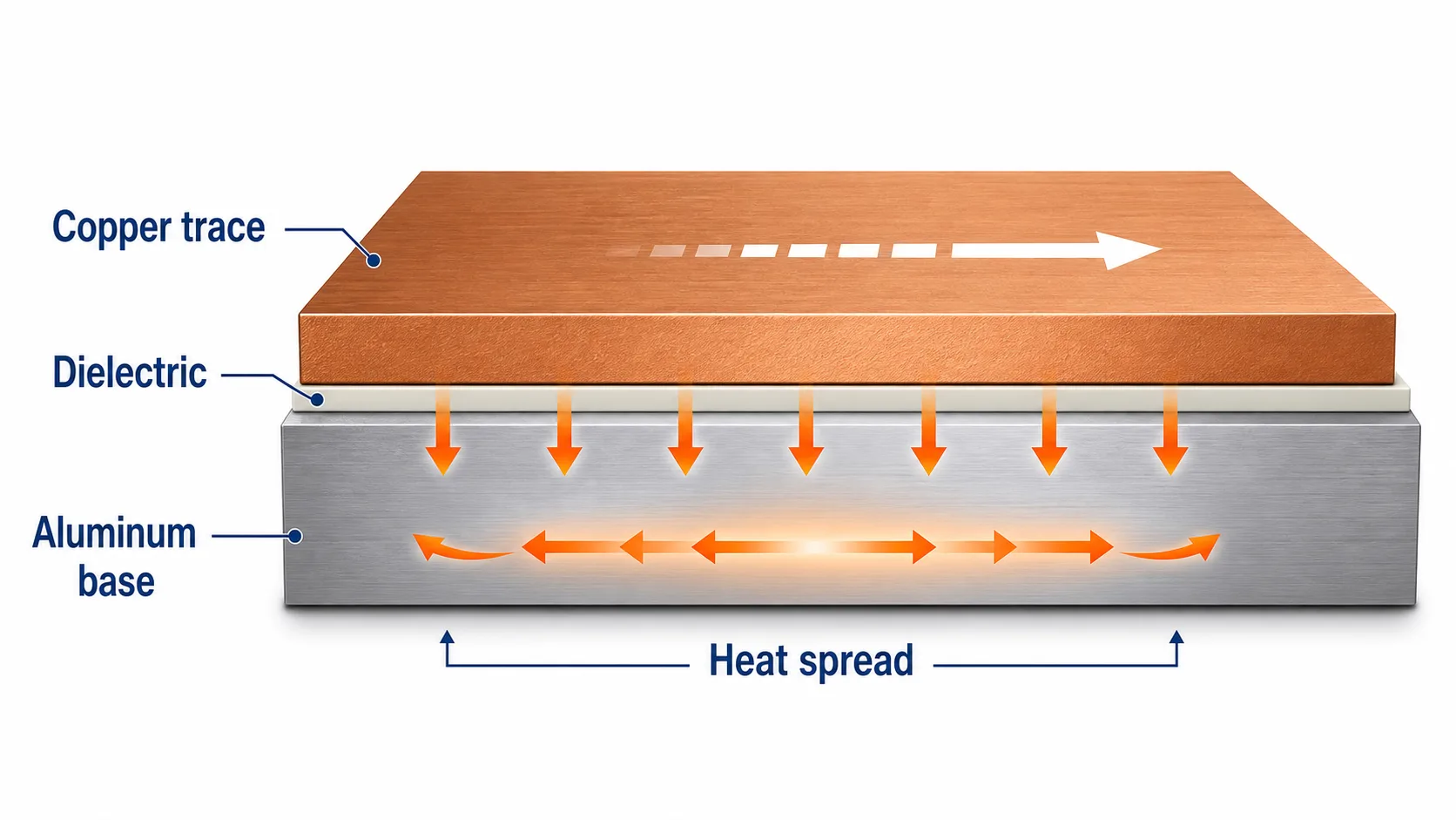 Current capacity depends on copper cross-section (width × thickness). The aluminum base helps heat spread, but it does not replace proper trace sizing.
| Copper | Approx. thickness | Relative area vs 1 oz (same width) |
|---|---|---|
| ~12 μm | ~12 μm | ~0.34× |
| 0.5 oz | ~18 μm | ~0.5× |
| 1 oz | ~35 μm | 1.0× |
| 2 oz | ~70 μm | ~2.0× |
This is a first-order size check for layout review.
A practical design flow looks like this:
- Know the continuous current on critical nets.
- Choose copper thickness.
- Size trace width and copper pour.
- Leave margin for dense areas and hot spots.
If you need reference tables by copper weight and width, see our LED aluminum PCB trace width article.
Changing copper thickness on the PO without checking the layout can create problems later.
Does Thicker Copper Always Cool LEDs Better?
No.
On an LED aluminum PCB, heat mainly moves like this:
LED pad → copper → dielectric → aluminum base → housing or heatsink.
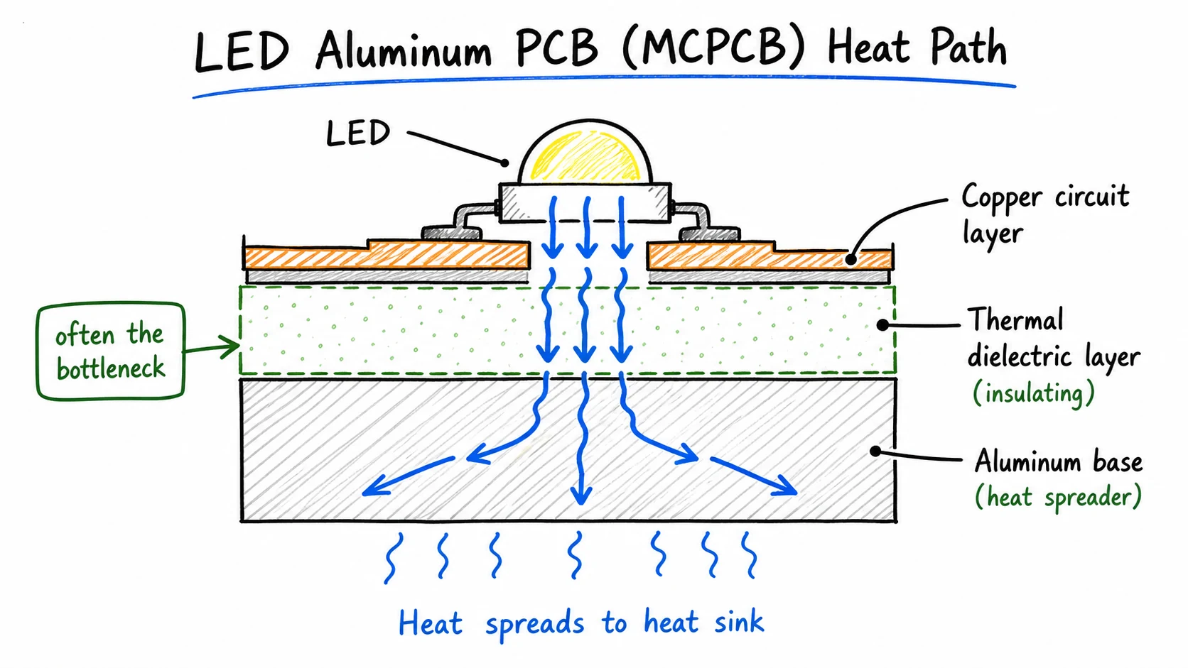 Through-plane heat often hits the dielectric first. Thicker copper mainly helps current capacity and lateral spreading—not automatic better LED cooling.
Cree’s XLamp PCB thermal application note shows that for MCPCB-style boards, the dielectric often limits through-plane thermal resistance, especially under small heat sources.
Copper has very high thermal conductivity.
The dielectric does not.
So making the copper much thicker gives only limited help on the vertical heat path compared with improving dielectric conductivity or thickness, or improving the board-to-housing interface.
IMS process notes make a similar point: high thermal conductivity and controlled dielectric thickness are key levers for heat transfer through the stack.
Thicker copper still helps in two ways:
- lower resistance in the conductor
- better lateral heat spreading under and around the LED pads
Those are real benefits.
They are not the same as “thicker copper = cooler LEDs.”
| Lever | Mainly improves | Check this first when… |
|---|---|---|
| Copper thickness | Current capacity, lateral spreading | High current on narrow routes |
| Dielectric | Through-plane heat transfer | Whole board or junction temp is high |
| Aluminum base / mounting interface | Heat into the lamp structure | Contact, grease, housing design is weak |
If a board runs hot, do not only write “change to thicker copper.”
Check copper area around the LEDs, dielectric choice, and how the board sits on the housing.
For more on the middle layer, see aluminum PCB dielectric.
When 12 μm Is Common — and When Drawings Use Thicker Copper
For many standard LED lighting boards, ~12 μm is a common production copper thickness.
If your drawing already calls for 1 oz or 2 oz, production follows that mark.
| Option | Approx. thickness | Common situation |
|---|---|---|
| ~12 μm | ~12 μm | Many volume single-sided LED aluminum boards |
| 0.5 oz | ~18 μm | Drawing or material menu uses half-ounce language |
| 1 oz | ~35 μm | Overseas drawings, IMS-style specs, higher current designs |
| 2 oz | ~70 μm | Designs that need more copper for current or spreading |
This table is for orientation only.
International IMS / LED notes often start the conversation at 18–35 μm and step to 70 μm when the design needs it.
Many volume LED aluminum boards still ship with ~12 μm when that is the agreed production thickness.
Heavier copper above 2 oz exists on some menus and IMS ranges.
IPC IMS fabrication notes also remind designers that heavier copper tightens process windows: wider min space, harder soldermask coverage, more etch compensation.
For routine LED lighting volume, thick copper is not our main product story.
A practical buyer rule:
- Drawing says 12 μm / thin copper → quote and build to that
- Drawing says 1 oz → build 1 oz
- Drawing has no copper thickness → confirm before production
- Do not treat thicker copper as a quality badge by itself
What to Put on the RFQ
For most quotes, copper is one of the basic board specs.
Buyers usually state copper thickness directly, or it is already on the Gerber / fabrication notes.
| Item | Example | Why it matters |
|---|---|---|
| Copper thickness | 12 μm, 1 oz, or as marked on the drawing | Price and production |
| Board size and quantity | e.g. 100 × 20 mm, 50k pcs | Volume cost and process |
| Aluminum thickness | e.g. 1.0 mm | Stackup and strength |
| Dielectric (if known) | Thickness / W/m·K | Material and thermal path |
| Surface finish | OSP / HASL / other | Assembly and storage |
| Gerber / drawing | With copper thickness marked if possible | Avoids guesswork |
Because nominal copper weight is not always finished copper, if you need a minimum finished copper thickness, write that clearly.
If copper is missing on the file, confirm it before production, then send the file for a fabrication quote.
Conclusion
Aluminum PCB copper thickness is a size choice for the copper circuit.
It is not a marketing grade.
International IMS and LED notes often talk in 0.5 oz / 1 oz / 2 oz.
Many volume LED aluminum boards still use ~12 μm as a common production thickness when the order is built that way.
Width and thickness work together for current capacity.
The dielectric and metal base still dominate through-board cooling.
Thicker copper can help current and lateral spreading.
It does not replace dielectric design or aluminum heat sinking.
If you need LED aluminum PCBs, send:
- drawing or Gerber
- copper thickness in μm or oz (as on the drawing)
- aluminum thickness
- board size and quantity
We will quote aluminum PCB fabrication for LED lighting to the copper thickness on your order—not the tallest number on a capability menu.
Need a quotation?
Send Gerber files and basic specifications. We reply within 1 business day.
Ask for Quote