LED Aluminum PCB Trace Width: Current Table for 0.5oz, 1oz, and 2oz

On This Page
LED Aluminum PCB Trace Width: Current Table for 0.5oz, 1oz, and 2oz
Aluminum PCB trace current depends on copper cross-section and temperature rise.
Not aluminum base thickness.
For most LED lighting projects, 1oz copper with a 0.5–2.0mm trace width covers common LED driver currents.
The aluminum core helps spread heat.
But treat that as extra safety margin.
Do not use it as a reason to cut trace width dramatically.
Use the reference tables below to choose trace width for 0.5oz, 1oz, and 2oz copper.
Why Trace Width Matters for LED Aluminum PCB
When current flows through a copper trace, it generates heat. That is I²R loss.
If the trace is too narrow for the current, the board gets hot. That heat can:
- Reduce LED life
- Weaken solder joints
- Stress the dielectric layer
Aluminum PCB helps dissipate heat at the system level. The metal core pulls heat away from components. But the trace itself still needs enough copper cross-section. The aluminum base does not eliminate the need for proper trace sizing.
In LED lighting, trace current is usually in the sub-amp to several-amp range per conductor. Not tens of amps. So standard copper thicknesses — 0.5oz to 2oz — are typically sufficient.
IPC-2221 Basics — The Standard Behind Trace Width Calculations
Most trace width calculators are based on IPC-2221. That is why this article uses an IPC-2221-style baseline first, similar to the method used in practical tools such as the AdvancedPCB trace width calculator and Altium's explanation of the IPC-2221 PCB trace current calculation.
For current-carrying design, however, IPC-2152 is the more useful engineering reference. The IPC-2152 table of contents makes clear that the standard is focused on current-carrying capacity in printed board design, while related IPC-2152 technical material treats conductor sizing as a thermal problem rather than only a width formula.
The formula uses current, temperature rise, and copper cross-section to estimate required width:
- External layer constant: k = 0.048
- Internal layer constant: k = 0.024
What this means in practice: internal layers need about twice the trace width for the same current. But on a single-sided aluminum PCB, all traces are on the external layer. So you use k = 0.048.
IPC-2221 is known to be conservative. It was developed from older board data. Modern boards with copper planes and aluminum cores can often run narrower traces. But the IPC-2221 baseline is still a safe starting point.
For production release, treat the tables in this article as quoting and design discussion references. Final compliance should be checked against the licensed IPC standard, customer reliability requirements, and the finished lamp thermal test.
Aluminum PCB vs FR4 — Does Better Heat Dissipation Help?
Yes, aluminum PCB traces run cooler than FR4 traces under the same current. But the improvement is modest. For a broader material comparison, see our Aluminum PCB vs FR4 guide.
Here is why.
The aluminum core has very high thermal conductivity — about 200 W/m·K. FR4 is about 0.3 W/m·K. So the aluminum core can spread heat much better.
But there is a bottleneck: the dielectric layer.
The dielectric sits between the copper trace and the aluminum base. Its thermal conductivity is typically 1–3 W/m·K. Much lower than the aluminum core. This limits how much heat can reach the aluminum base. For more on this layer, read our guide to aluminum PCB dielectric material.
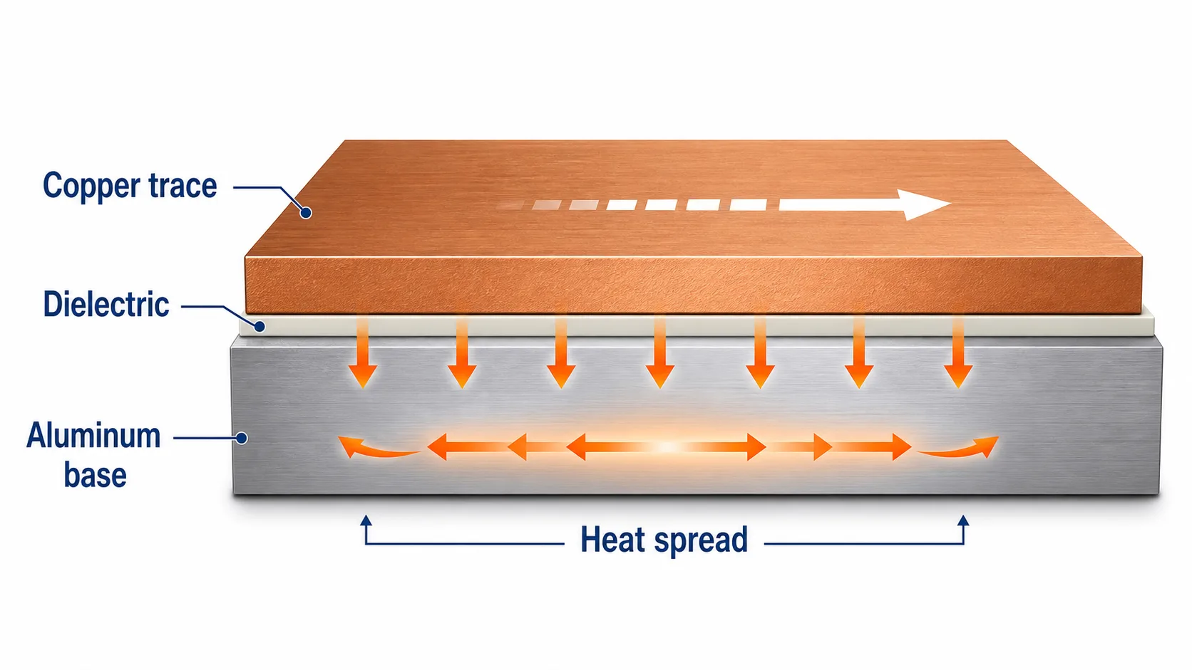 The aluminum base helps spread heat, but current capacity still depends mainly on copper trace cross-section and allowed temperature rise.
The important point from IPC-2152 technical guidance is that conductor temperature rise is affected by board material, board thickness, copper planes, copper thickness, mounting, and environment. That is why finished-board testing and layout context still matter even when a quick IPC-2221-style table is used for early sizing.
Practical takeaway: Aluminum PCB can carry somewhat higher current than FR4 at the same trace geometry. But the gain is incremental. Treat it as extra safety margin — not a reason to dramatically reduce trace width.
Trace Width vs Current Reference Table — 0.5oz / 1oz / 2oz
The tables below are based on IPC-2221 as a conservative baseline.
Use them as starting estimates, not final thermal test results.
Assumptions:
- External-layer trace
- Single-sided aluminum PCB layout
- IPC-2221 style conservative calculation
- Trace current estimated by copper cross-section and allowed temperature rise
- No special credit taken for enclosure airflow, copper pours, or heatsink contact
Actual current capacity can change with trace length, copper pours, ambient temperature, dielectric material, board mounting, and the final lamp housing.
10°C Temperature Rise
| Trace Width (mm) | 0.5oz (A) | 1oz (A) | 2oz (A) |
|---|---|---|---|
| 0.2 | 0.46 | 0.74 | 1.23 |
| 0.3 | 0.61 | 0.99 | 1.64 |
| 0.5 | 0.89 | 1.44 | 2.38 |
| 0.8 | 1.25 | 2.03 | 3.34 |
| 1.0 | 1.46 | 2.38 | 3.94 |
| 1.5 | 1.96 | 3.20 | 5.30 |
| 2.0 | 2.42 | 3.94 | 6.56 |
| 3.0 | 3.25 | 5.28 | 8.80 |
| 5.0 | 4.70 | 7.65 | 12.76 |
20°C Temperature Rise
| Trace Width (mm) | 0.5oz (A) | 1oz (A) | 2oz (A) |
|---|---|---|---|
| 0.2 | 0.62 | 1.01 | 1.66 |
| 0.3 | 0.83 | 1.35 | 2.23 |
| 0.5 | 1.20 | 1.95 | 3.23 |
| 0.8 | 1.69 | 2.75 | 4.57 |
| 1.0 | 1.99 | 3.23 | 5.37 |
| 1.5 | 2.66 | 4.33 | 7.19 |
| 2.0 | 3.28 | 5.34 | 8.86 |
| 3.0 | 4.40 | 7.17 | 11.89 |
| 5.0 | 6.38 | 10.38 | 17.21 |
30°C Temperature Rise
| Trace Width (mm) | 0.5oz (A) | 1oz (A) | 2oz (A) |
|---|---|---|---|
| 0.2 | 0.74 | 1.20 | 1.99 |
| 0.3 | 0.99 | 1.61 | 2.67 |
| 0.5 | 1.44 | 2.34 | 3.87 |
| 0.8 | 2.02 | 3.28 | 5.43 |
| 1.0 | 2.37 | 3.86 | 6.39 |
| 1.5 | 3.18 | 5.18 | 8.58 |
| 2.0 | 3.92 | 6.38 | 10.57 |
| 3.0 | 5.26 | 8.56 | 14.18 |
| 5.0 | 7.62 | 12.40 | 20.54 |
How to use this table:
Find your target current. Choose your copper thickness. Read the trace width for your allowed temperature rise.
For example, a 1oz trace at 1.0mm width:
- Carries about 2.38A at 10°C rise
- Carries about 3.23A at 20°C rise
- Carries about 3.86A at 30°C rise
When to pick which temperature rise:
- 10°C: High reliability, tight thermal budget
- 20°C: Typical for commercial LED products
- 30°C: Possible with good cooling
These are starting estimates. IPC-2152 shows that board material, thickness, copper planes, and environment can change allowable current.
0.5oz / 1oz / 2oz — Which Copper Thickness Should You Choose?
For most LED lighting applications, 1oz copper is the sweet spot. It handles the 1A–3A range most LED drivers use. It is cost-effective and widely available.
This also fits common IMS manufacturing guidance. For example, Würth Elektronik's IMS design rules show typical metal-core PCB copper options from 0.5oz to 4oz, with line-width and insulation-layer limits changing as the stackup becomes heavier.
| Copper | Best For | Max Current* | Cost vs 1oz |
|---|---|---|---|
| 0.5oz | Low-power, <0.5A | ~2.0A | Slightly lower |
| 1oz | Standard LED, 1–3A | ~3.2A | Baseline |
| 2oz | High-power, 3A+ | ~5.3A | ~1.3–1.5× |
*At 1.0mm trace width, 20°C rise.
0.5oz (18μm)
Use for low-power designs. Current under 0.5A. Cost-sensitive boards. Fine etching is possible — minimum line width 3mil.
Good for: indicator lights, low-power LED strips, control circuits.
1oz (35μm)
The standard for LED lighting. Covers 1A–3A. Minimum line width 4mil. Enough for many standard LED boards.
This is what most aluminum PCB factories stock as standard. Lead time is shortest for 1oz.
2oz (70μm)
Use for high-current paths over 3A. Or when voltage drop is a concern on long traces.
But 2oz adds cost — about 1.3 to 1.5 times 1oz. It also adds manufacturing complexity. Minimum line width is 5mil, spacing is 7mil.
Do not over-spec to 2oz "just in case." For most LED designs, 1oz is enough.
Manufacturing Tolerances — Why Your Trace Width Needs Margin
In mass production, trace width is never exactly the CAD value.
Etching and copper thickness variation change the final width. A trace designed at 1.0mm may finish at 0.8mm. That is a 20% reduction in copper cross-section.
What that means: the trace will run hotter than expected.
Published fabrication limits show why this margin matters. AdvancedPCB's tolerance guidance lists trace and spacing control as a production variable, and PCBWay's PCB manufacturing tolerances give a similar reminder that finished dimensions are not identical to CAD nominal values.
Typical tolerances:
- Trace width: ±20% or ±0.002in (whichever is greater)
- Copper thickness: ±10% of nominal
Minimum line width by copper thickness:
| Copper | Outer Min. Width | Outer Min. Spacing |
|---|---|---|
| 0.5oz | 3mil | 4mil |
| 1oz | 4mil | 5mil |
| 2oz | 5mil | 7mil |
Notice how the minimums increase with copper thickness. This is another reason not to over-spec.
Practical advice: For power traces, design for the worst-case finished width. Add 20–30% margin above the table value.
LED Lighting Scenario Map
Here is how the reference table maps to real LED power levels.
| Application | Typical Current | Recommended Copper | Typical Trace Width |
|---|---|---|---|
| 5W LED board | <0.5A | 0.5oz–1oz | 0.2–0.5mm |
| 10W LED board | 0.5–1.0A | 1oz | 0.3–0.8mm |
| 30W LED board | 1.0–2.0A | 1oz–2oz | 0.5–1.5mm |
| 50W LED board | 2.0–3.0A+ | 2oz | 1.0–2.0mm |
These are typical ranges. Actual trace width also depends on trace length, number of parallel traces, and whether wide copper pours are used. If board thickness is also unclear, compare this with our LED aluminum PCB thickness guide.
For most designs within these ranges, 1oz copper with moderate trace width is sufficient.
Common Mistakes When Designing Traces for LED Aluminum PCB
1. Assuming the aluminum core allows very narrow traces
It does not. The dielectric layer is the thermal bottleneck. The aluminum core helps, but not enough to justify extremely narrow traces. Use the reference table.
2. Over-specifying copper weight "just in case"
2oz adds cost and complexity. For most LED designs, 1oz is enough. Only go to 2oz when current exceeds 3A or voltage drop is a concern.
3. Ignoring etching tolerance
A 1.0mm trace may finish at 0.8mm. Design for the worst case. Add margin.
4. Using FR4 trace rules on aluminum PCB
IPC-2152 shows the material effect is modest. Do not assume you can cut trace width dramatically just because it is aluminum PCB.
5. Using "1mm per amp" as a rule
That is a rough starting point. Not a substitute for checking the table and your actual temperature rise requirement.
Conclusion
Trace current on an aluminum PCB comes down to copper cross-section and temperature rise.
The aluminum core helps.
But the gain is modest.
For most LED lighting projects:
- Use 1oz copper as your default
- Pick 0.5–2.0mm trace width based on the reference table
- Go to 2oz copper only when current exceeds 3A
- Always design with 20–30% margin for manufacturing tolerances
- Do not over-spec copper thickness "just in case"
If you are not sure whether 0.5oz, 1oz, or 2oz copper is enough, send your LED board drawing, target current, board thickness, copper thickness, surface finish, quantity, and application to Lumina Technology.
We can help check trace width, copper thickness, and production margin before mass production.
Join Our Industrial Community
Get exclusive technical whitepapers and industry news delivered to your inbox every month. No spam, only professional insights.