How to Choose SMT Solder Paste for LED Aluminum PCB Assembly

On This Page (Table of Contents)
For standard LED aluminum PCB assembly, you don’t usually need special aluminum solder paste. The paste is printed on finished copper pads above the dielectric layer. That’s why an aluminum PCB doesn’t automatically call for a specialty solder paste. See our guide on aluminum PCB manufacturing for more context.
Both leaded and lead-free pastes can be valid when the approved product and process requirements allow them.
This guide walks through the main paste options, which process details actually matter, and what you should verify before moving to sample or mass production.
You Are Soldering to Copper Pads — Not the Aluminum Base
In a normal single-sided LED aluminum PCB, solder paste sits on the copper pads. The aluminum core stays below the dielectric and is rarely involved in the actual soldering.
A typical joint looks like this:
- LED or component termination
- Reflowed solder joint
- Surface-finished copper pad
- Dielectric layer
- Aluminum base
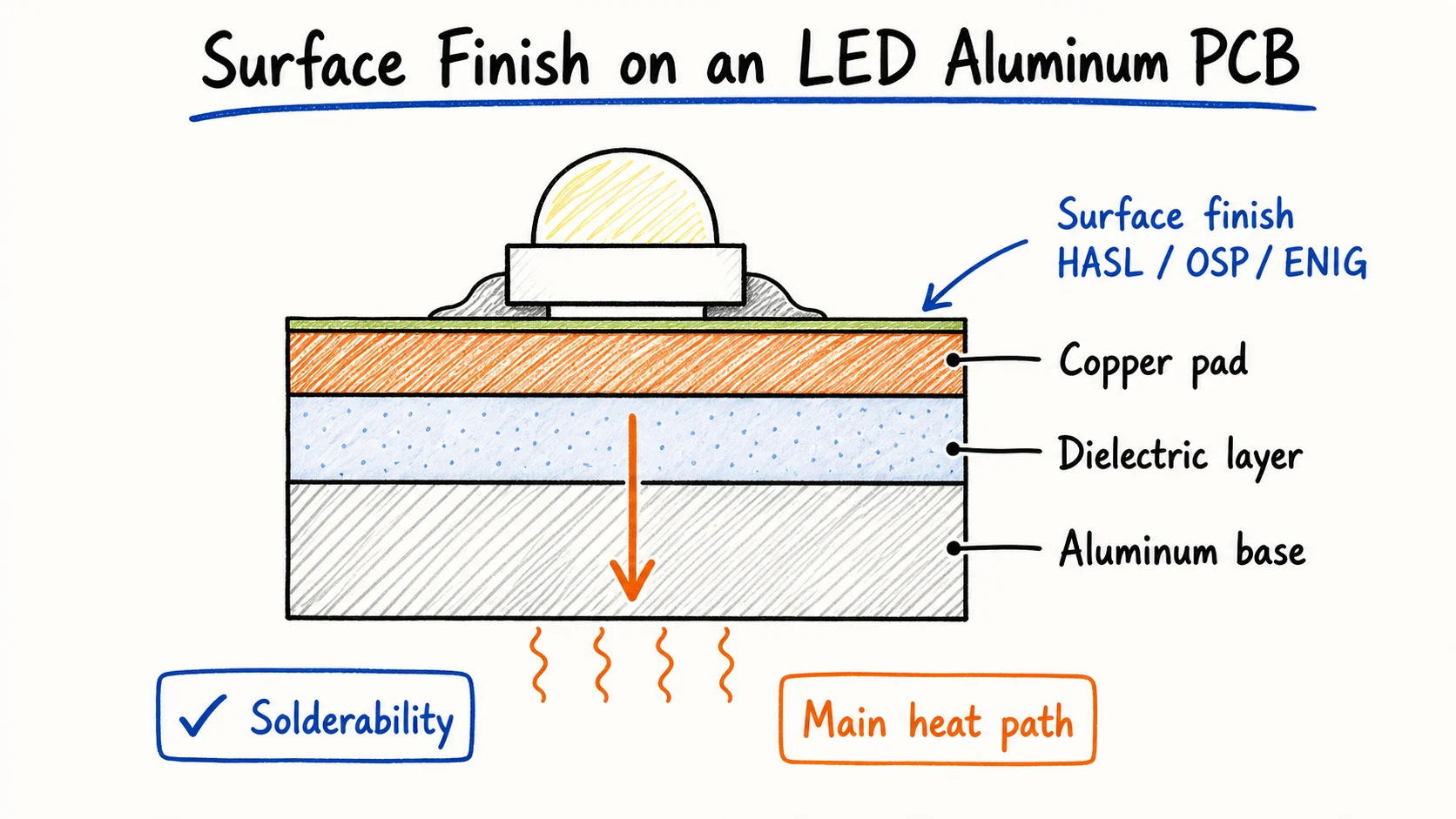 The solder joint forms on the finished copper pad—not on the aluminum base.
The copper pad finish (OSP, HASL, ENIG, etc.) affects storage, wetting, and flatness. In the standard LED aluminum PCB structure discussed here, the joint forms on the finished copper pad.
Direct soldering to exposed aluminum is a completely different process that requires special fluxes or surface treatment. That’s not what you’re doing on standard LED boards.
Leaded vs Lead-Free Paste: Start With the Product Requirement
Pick leaded or lead-free first based on the approved build spec, target market, and compliance needs.
Neither family is automatically better.
Common examples are Sn63/Pb37 (leaded) and SAC305 (lead-free). These are just industry references — not defaults for every factory or every LED board.
When leaded paste can be considered
Use it when the customer allows it and the market doesn’t require lead-free.
Common SnPb pastes often have a lower reflow temperature and can offer better wetting in some processes.
When lead-free paste is usually required
Choose it for RoHS-style requirements or markets that demand it.
SAC-family paste runs hotter, so the LED package must support it. A “lead-free” label alone is not enough — the alloy, flux, finish, and profile all need to work together.
| Decision Factor | Leaded Paste | Lead-Free Paste | What to Confirm |
|---|---|---|---|
| Build specification | Only if permitted | Often required | Approved alloy or restrictions |
| Target market | May face restrictions | Common for RoHS | Destination market requirements |
| Reflow temperature | Usually lower | Usually higher | Paste data + LED limits |
| Wetting margin | Can be more forgiving | Needs tight control | Actual materials and process |
| Production controls | Needs contamination control | Needs contamination control | Tools, rework, and changeover |
Low-temperature alloys (like SnBi) exist but are not a general upgrade for aluminum PCBs. Use them only when you have a specific, qualified process need.
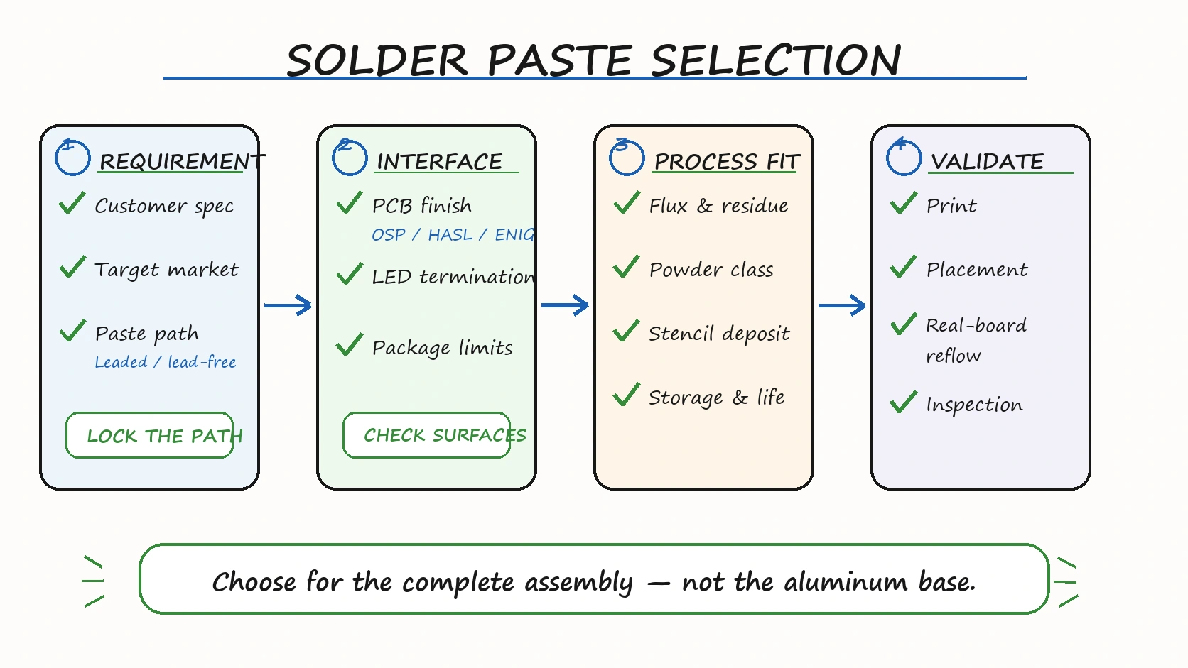 Start with the product requirement, then check the joint interfaces, factory process, and actual-board validation.
Alloy Is Only One Part of the Story
The alloy sets the metallurgical foundation. The flux vehicle and powder size control how the paste actually prints, holds, wets, and reflows.
Two pastes with the same alloy can behave very differently on the line.
Flux and residue
Flux removes oxides, promotes wetting, and controls residue. Flux chemistry is a production decision, not a minor ingredient.
- No-clean pastes reduce washing needs but don’t mean zero residue.
- Water-soluble pastes require a validated wash and dry step.
- Halide restrictions usually come from the customer spec.
Powder class and stencil
Powder size must match your stencil thickness and aperture geometry. Finer powder isn’t always better — it depends on your process.
Storage and working life
Follow the manufacturer’s instructions for storage, thawing, and opened-container life. Poor handling is a common source of print problems.
Match the Paste to PCB Finish and LED Termination
A paste only works when it wets the actual PCB finish and LED termination inside the allowed reflow window.
OSP
A flat, cost-effective copper surface. Performance depends heavily on storage condition and oxidation level.
HASL and lead-free HASL
Pads already carry solder, but topography can matter for small LEDs or tight coplanarity.
ENIG
Provides excellent flatness. It may be worth it for fine-pitch or high-coplanarity needs, but for simple LED boards it often adds unnecessary cost. See our ENIG aluminum PCB guide for details.
| PCB Finish | Main Consideration | When It May Be Worth Checking |
|---|---|---|
| OSP | Storage, oxidation, and flux | Finish age and actual wetting |
| HASL/LF-HASL | Solderability and pad flatness | LED package size and placement needs |
| ENIG | Flatness and finish quality | Coplanarity and supplier quality |
The LED manufacturer’s soldering note is just as important as the PCB finish.
LED Thermal Pads Make Stencil Design Critical
Even the right paste can fail if the stencil deposits too little or too much paste, or if it doesn’t allow flux to escape.
Thermal pads are especially sensitive to aperture pattern and paste volume. Too much or uneven paste can contribute to bridging or tilt. Too little can produce incomplete coverage. Voiding, however, can also be affected by pad design, flux behavior, reflow conditions, and component geometry.
Common good practices include segmented apertures or window-pane designs. Always start with the LED package’s recommended land pattern.
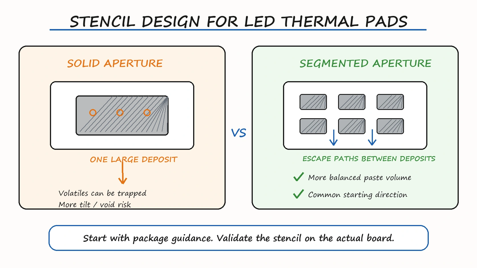 Segmented apertures are a common starting direction, but the final design still requires package-specific validation.
Match the Paste and Reflow to the Actual Aluminum PCB
The aluminum core changes heat spreading, but the final reflow profile still depends on board size, panel loading, component mass, and oven setup.
An aluminum PCB doesn’t always need a higher peak temperature or longer soak. Those decisions should come from actual measurements on representative boards.
See our guide on reflow soldering aluminum PCB for more details.
A change in paste can also affect printing and reflow even if the alloy stays the same. A meaningful change may require process review or revalidation.
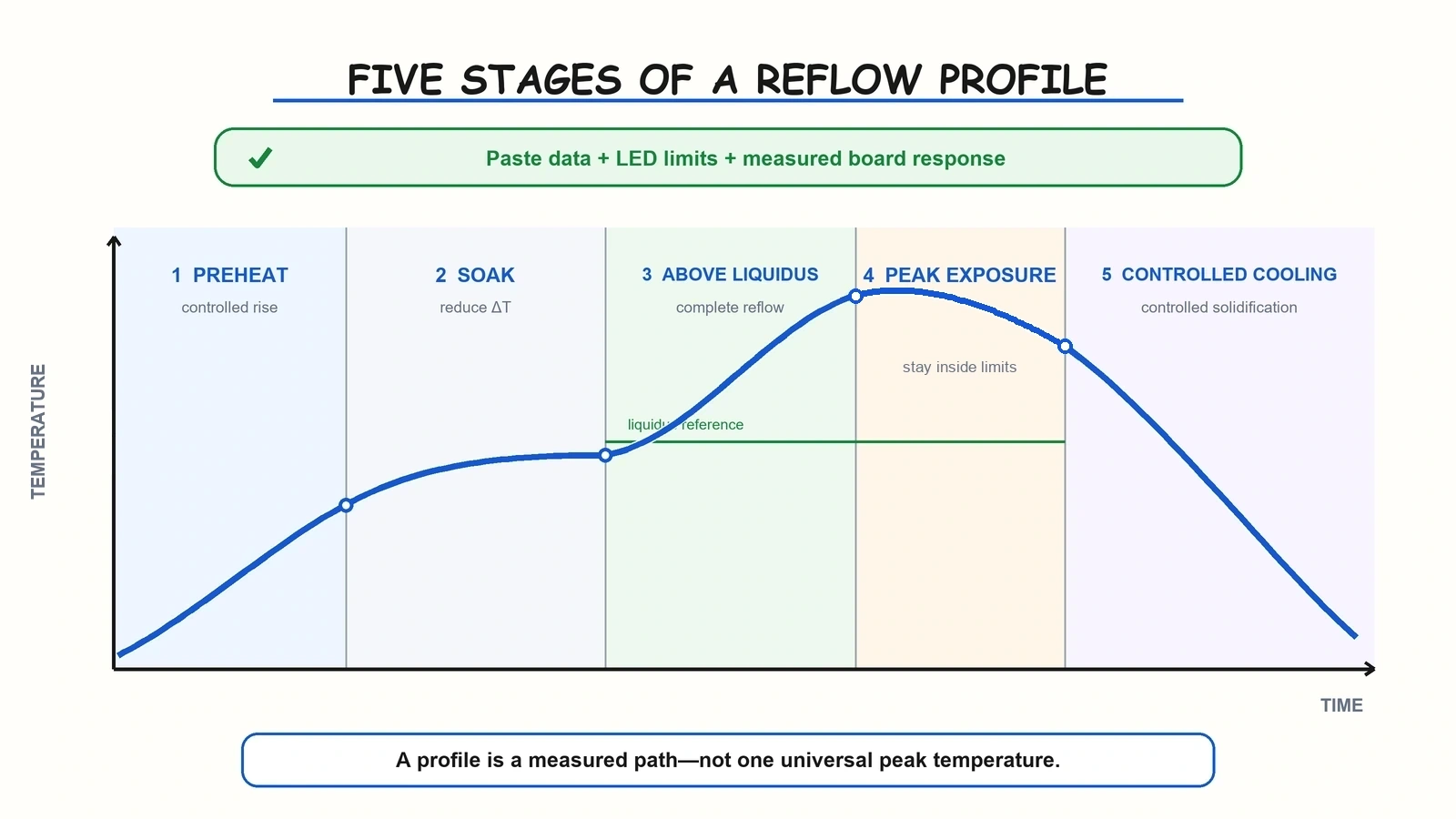 A reflow profile should combine paste guidance, LED limits, and measured board response.
Simple Flow to Choose the Right Paste
- Lock the compliance path (leaded or lead-free).
- Record the PCB surface finish and exact LED termination.
- Check the LED package’s recommended soldering process and temperature limits.
- Align the flux, residue, powder class, stencil, and storage requirements with your factory process.
- Validate paste deposit, placement, and reflow on actual boards.
- Define clear rules for substitutions before repeat production.
What to Provide Before Mass Production
A Gerber file alone is normally not enough for an assembled LED board. Send the following instead:
Product & compliance
- target market
- leaded or lead-free requirement
- approved alloys or restrictions
- required material or compliance documents
Board
- Gerber, surface finish, panel size, copper weight
Components
- BOM, pick-and-place file, exact LED datasheets, assembly notes
Process
- residue/cleaning requirement, stencil data, approved profile if available, agreed inspection method
Change control
- what substitutions are allowed and who approves them
Choose the Paste for the Complete Assembly
Standard LED aluminum PCBs normally use conventional SMT solder paste on finished copper pads. The aluminum base mainly affects heat spreading — it doesn’t require special paste.
Pick leaded or lead-free according to the product requirement. Then make sure the flux, powder, finish, LED package, stencil, and actual reflow process all work together.
If you’re preparing a new single-sided aluminum LED light board with a specific quantity and application, send your Gerber files, BOM, pick-and-place, LED datasheets, surface finish, target market, and any solder-paste or cleaning requirements.
Lumina can first review whether the project fits its aluminum PCB + SMT assembly scope before quotation and sample production. See our LED PCB assembly quote guide for details.
Need a quotation?
Send Gerber files and basic specifications. We reply within 1 business day.
Ask for Quote