Reflow Soldering Aluminum PCBs: Process Controls for LED Assembly

On This Page (Table of Contents)
When reflow soldering an aluminum PCB for LED assembly, do not assume the oven recipe from FR4 moves with it.
The metal-core stack spreads heat differently. Board thickness, panel size, copper distribution, and component population also change how the assembly heats and cools.
That does not mean every aluminum PCB needs a hotter profile.
It means the profile should be checked on the real board—not copied from the last FR4 job.
The useful control order is simple: start with the solder paste guidance, check the LED package limits, and then measure what happens at the hottest and coldest locations on the actual assembly.
One detail is also easy to miss: normal SMT soldering happens on the finished copper pads, not on the aluminum base.
This guide explains what changes, what can go wrong, and what buyers should confirm before sample or batch production.
You Are Soldering to Copper Pads—not the Aluminum Base
The name “aluminum PCB” causes a lot of confusion.
In a normal LED SMT process, solder paste is still printed on finished copper pads. The aluminum stays below the dielectric and does not become the regular soldering surface.
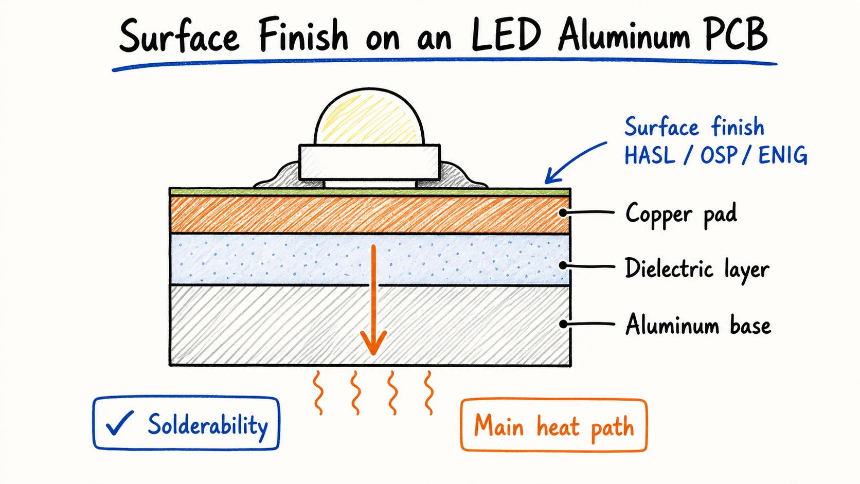 During normal MCPCB reflow, the solder joint forms on the finished copper pad—not on the aluminum base.
A typical single-sided aluminum PCB has three functional layers:
- a copper circuit layer on top
- an electrically insulating, thermally conductive dielectric in the middle
- an aluminum base underneath
The component termination joins to the copper pad during reflow.
That copper may have OSP, lead-free HASL, ENIG, or another specified finish. The finish affects solderability, storage, and pad condition, but the solder joint is not being made directly to the aluminum base.
| Surface or Layer | Role During Assembly |
|---|---|
| Finished copper pad | Receives solder paste and the component termination |
| Dielectric | Electrically isolates copper from aluminum and transfers heat |
| Aluminum base | Spreads heat and supports the board mechanically |
Direct soldering to bare aluminum is a different process. It has its own oxide and wetting problems and may require specialized methods.
That information should not be used as the reflow guide for a standard LED MCPCB.
If you need more context on the copper-side finish, see our aluminum PCB surface finish guide. For the basic board construction, start with our single-sided aluminum PCB for LED lighting page.
The first distinction is therefore straightforward: aluminum changes the board structure and heat path, but normal SMT still solders to copper pads.
Why an FR4 Reflow Profile May Not Transfer to Aluminum PCB
The board may fit the same oven, but that does not mean it should use the same settings.
An aluminum PCB can distribute heat differently from FR4. The metal base spreads heat across the board, while the full assembly response also depends on its size, thickness, copper layout, components, panel design, and oven loading.
This is where two ideas often get mixed together:
- thermal conductivity describes how readily a material conducts heat
- thermal mass and assembly response describe how the complete build heats and cools in the process
They are related, but they are not the same thing.
A small aluminum LED board and a large production panel may use a similar material stack and still behave differently in the oven. A board with large copper areas or large thermal pads can also create different hot and cold locations from a lightly populated board.
Some controls stay the same when you move from FR4 to aluminum PCB. What changes is how the real board may respond inside that window.
| Process Check | What Stays the Same | What May Change on Aluminum PCB |
|---|---|---|
| Soldering surface | Components solder to finished copper pads | The aluminum base changes the heat path, not the soldering surface |
| Paste limits | The paste datasheet defines the process window | The board may reach that window differently |
| Component limits | LED package limits still apply | The metal core does not raise those limits |
| Board response | Size, layout, components, and loading matter on any PCB | The aluminum base can spread heat differently from FR4 |
| Verification | A changed build should be checked on the real assembly | Do not reuse an FR4 profile without measurement |
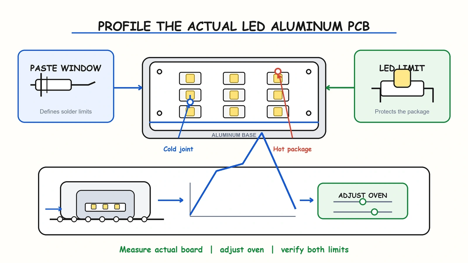 The useful profile is measured on the real assembly and checked against both paste and LED package limits.
So should you automatically increase preheat or peak temperature?
No.
Some aluminum PCB assemblies may need a different ramp, soak, conveyor speed, or zone setting. But the correct adjustment comes from measured results and process limits—not from a rule that says “metal-core means more heat.”
A copied FR4 profile can fail in either direction. The coldest joint may not receive enough reflow exposure, or the operator may compensate too aggressively and push a sensitive LED package closer to its limit.
The better question is not “What is the standard aluminum PCB temperature?”
It is “Does this actual assembly stay inside the paste and component window from its coldest joint to its hottest package?”
For a deeper explanation of how the metal-core stack moves heat, read how LED aluminum PCB heat dissipation works.
Build the Profile Around the Paste, LED, and Real Board
You do not need a mysterious “aluminum PCB temperature.”
You need a working window that starts with the paste and LED limits, then proves that the coldest joint reflows without pushing the hottest package too far.
A practical control order is:
- Check the solder paste manufacturer’s recommended profile window.
- Check the reflow limits for the exact LEDs and other sensitive components.
- Confirm moisture sensitivity and floor-life requirements.
- Profile a representative production assembly.
- Adjust the oven only after reviewing the measured curve.
AIM Solder’s reflow profile guidance is a useful reminder that ramp, soak, time above liquidus, peak, and cooling belong to one process window.
The oven setpoint is only an input. What matters is the temperature history experienced by the real solder joints and component packages.
Preheat and Soak Should Reduce Temperature Differences
Preheat and soak should bring the assembly toward a more even temperature while allowing the flux to work inside its intended window.
A controlled ramp helps reduce abrupt thermal stress. A suitable soak can reduce the temperature difference between light and heavy areas of the assembly.
But longer is not automatically better.
Holding the board too long can consume the flux too early or increase oxidation risk. The paste supplier’s guidance still matters, even when the board has a metal core.
The purpose is temperature control—not simply adding more heat because the board is aluminum.
Time Above Liquidus Must Work at the Coldest Joint
The coldest solder joint must receive enough time above liquidus for the solder to reflow properly.
At the same time, the hottest component must remain inside its permitted exposure.
This is why measuring only the oven air temperature is not enough. A zone may be set correctly while a thermally demanding location on the board responds differently.
Too little time above liquidus can contribute to incomplete reflow or weak wetting.
Too much exposure can increase oxidation, flux exhaustion, excessive intermetallic growth, or component risk.
The selected paste datasheet should provide the numeric window. The actual board profile should show whether the coldest joint meets it.
Peak and Cooling Must Stay Inside the Qualified Window
The peak should satisfy the soldering process without exceeding the limits of the LED and other components.
Remember that the LED package-body temperature is not necessarily the same as the solder-joint temperature.
Cooling also belongs to the controlled process. An abrupt transition can add thermal stress, while an unsuitable cooling rate can affect solder solidification.
Again, there is no single value that applies to every aluminum LED board.
The ams OSRAM application note on lead-free reflow soldering of LEDs gives manufacturer-level guidance on package temperature, ramp behavior, reflow exposure, and moisture handling. Use such values for the applicable package—not as a universal Lumina oven recipe.
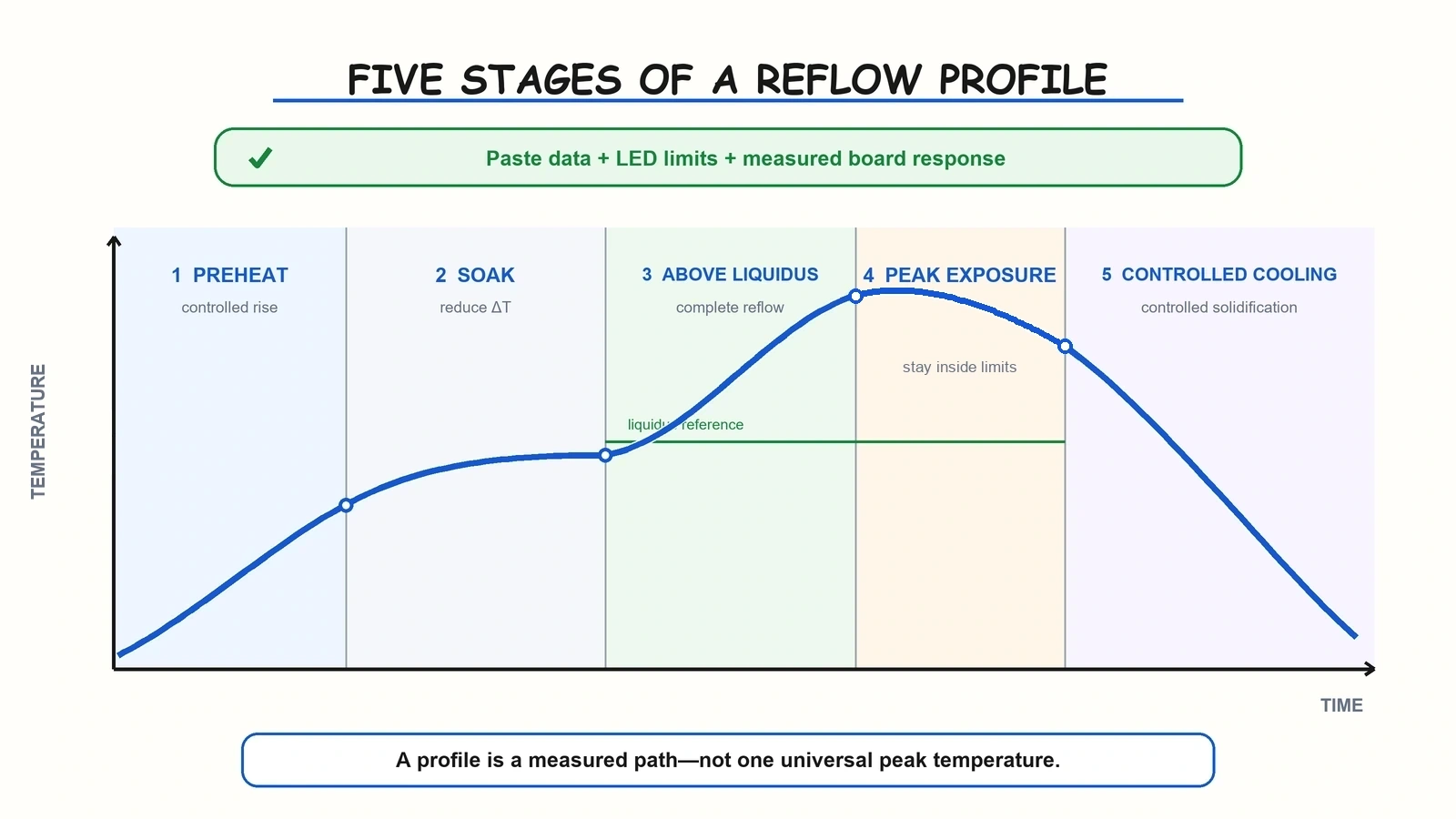 A reflow profile is a controlled path through preheat, soak, liquidus, peak, and cooling—not one universal temperature.
| Profile Stage | Main Goal | Common Mistake |
|---|---|---|
| Preheat | Raise temperature in a controlled way | Ramping aggressively to compensate for the metal core |
| Soak | Reduce temperature differences and activate flux | Holding too long without paste support |
| Time above liquidus | Complete reflow at the coldest joint | Checking oven settings instead of joint temperature |
| Peak | Stay inside paste and component limits | Treating a qualification maximum as the production target |
| Cooling | Control solidification and thermal stress | Ignoring paste and component guidance |
The profile is not one temperature number. It is the measured path through all five stages.
The LED Package Still Sets the Reflow Limit
The aluminum base may change how heat moves through the board.
It does not give the LED package a higher temperature limit.
The exact LED datasheet and moisture sensitivity status still control package exposure, floor life, storage, and any required drying.
This matters because LEDs can be moisture-sensitive devices. If a package remains outside controlled storage longer than allowed, moisture can increase the risk of cracking or delamination during reflow.
A hotter or longer profile does not solve that problem and can make it worse.
Before assembly, confirm:
- the exact LED manufacturer and package code
- its reflow guidance
- moisture sensitivity level, where applicable
- remaining floor life
- storage and dry-pack condition
- whether drying is required by the manufacturer’s instructions
Do not apply one LED manufacturer’s peak temperature or ramp limit to every package.
The useful rule is simpler: the selected component document sets the ceiling. The actual aluminum PCB profile must remain below it while still completing solder reflow at the coldest joint.
If you are sending a project for quotation, include the actual LED datasheets rather than only a generic BOM description. Our LED PCB assembly quote guide explains why complete assembly files reduce back-and-forth before production.
When Reflow Is Off, the Aluminum PCB Is Not Always the Only Cause
A weak joint does not automatically mean the aluminum PCB is the problem.
The profile may be involved, but paste, finish condition, stencil design, placement, storage, and contamination can create similar symptoms.
That distinction matters during troubleshooting.
If every defect is blamed on the board’s heat spreading, the process team may keep changing oven settings while the real problem sits in paste printing or material handling.
| Symptom | Possible Link | First Checks |
|---|---|---|
| Incomplete joint | A cold location missed the required reflow window | Measured time above liquidus and paste guidance |
| Poor wetting | Heat, finish, contamination, or flux issue | Finish condition, storage, paste, and measured profile |
| Voiding | Paste, stencil, thermal pad, and profile interaction | Aperture design, paste type, and profile |
| Bridging or solder balls | Printing, placement, and profile interaction | Paste volume and placement before blaming the board |
| LED package damage | Peak, ramp, or moisture-handling issue | LED limits, MSL, floor life, and storage |
An incomplete-looking joint may point to insufficient exposure at a cold location.
Poor wetting can also come from oxidized pads, unsuitable storage, contamination, or flux behavior.
Voiding on a large LED thermal pad is rarely a one-variable problem. Paste chemistry, stencil apertures, component geometry, and profile all interact.
The same applies to bridging and solder balls. Check printing and placement before trying to “fix” everything with more oven heat.
Visual appearance helps you decide where to investigate, but it does not prove the root cause by itself.
For buyers, the important point is to ask how the supplier separates board, material, printing, placement, and profile causes before moving into batch production.
What Buyers Should Confirm Before Mass Production
Before you approve a batch, ask how the process was verified on your actual build.
For a new or materially changed build, a stable process normally starts with a representative thermal profile and first-article verification. Repeat production still needs review when the board, paste, component, panel, or oven loading changes.
You do not need to ask for a thick process report on every simple LED board.
You do need clarity about what was checked and what is included.
Useful questions include:
- Was the thermal profile measured on the real panel or a representative production build?
- Where were the hottest and coldest measurement points?
- Were both paste limits and component limits checked?
- What changes would trigger a new profile or process review?
- Which visual, AOI, electrical, or functional checks are included?
- Is a sample or first-article approval required before the batch order?
| Control Question | Why It Matters | What to Clarify |
|---|---|---|
| Was the real build profiled? | Confirms the actual thermal response | New profile, existing qualified process, or project review |
| Was a first article checked? | Finds mismatch before the batch grows | Inspection and approval scope |
| What triggers re-evaluation? | Prevents an old process being reused after a change | Board, paste, LED, panel, or loading revisions |
| Which inspections are included? | Avoids assumptions between buyer and supplier | Visual, AOI, electrical, and functional scope |
Inspection scope should be confirmed project by project.
For example, AOI can help find placement and visible soldering problems. It does not replace every electrical or functional test, and it does not automatically prove that a thermal profile was correct.
The goal is not to collect the longest inspection list. It is to define enough control for the product, then keep that process stable when repeat orders arrive.
You can review our LED aluminum PCB assembly service for the general service path. Specific profiling, inspection, and testing requirements should still be confirmed before quotation.
What to Send Before Aluminum PCB + SMT Production
A Gerber file tells the factory how to make the board.
It does not tell the whole assembly story.
Send the assembly files, exact LED documentation, and any process or acceptance requirements with it.
Board Data
- Gerber files or fabrication drawing
- board and panel dimensions
- total board thickness and known stackup requirements
- copper thickness
- surface finish
Assembly Data
- BOM
- pick-and-place or centroid file
- assembly drawing
- LED polarity and orientation notes
- exact LED and sensitive-component datasheets
- solder paste, alloy, or compliance requirement if already specified
Order and Acceptance Data
- sample or batch quantity
- required visual, electrical, or functional checks
- moisture or storage requirements
- existing approved profile, if the project already has one
- known failure history, if the design is being transferred or corrected
Not every project needs every optional item.
But missing LED data, polarity information, or acceptance requirements can create avoidable questions after production has already started.
For a new design, sample validation is the practical bridge between a technically reasonable profile and stable batch production.
That is also where the buyer and supplier can confirm whether the project fits the intended single-sided aluminum PCB fabrication and LED PCB assembly scope.
Conclusion
Reflow soldering an aluminum PCB is not about finding one hotter temperature curve.
It is about controlling the full process window:
- solder to the finished copper pads
- start with the paste guidance
- respect the exact LED package and moisture limits
- profile the real aluminum PCB assembly
- verify the coldest joint and hottest package
- confirm first-article and inspection scope before the batch
An FR4 profile may provide a starting reference, but it should not be treated as proof that the aluminum PCB assembly is ready for production.
If you are preparing a single-sided aluminum PCB with LED assembly, send the Gerber files, BOM, pick-and-place file, LED datasheets, board specification, quantity, and required checks.
We will first confirm whether the project fits our aluminum PCB + SMT scope, then clarify what still needs to be checked before quotation and sample production.
Need a quotation?
Send Gerber files and basic specifications. We reply within 1 business day.
Ask for Quote