How LED Aluminum PCB Heat Dissipation Really Works

On This Page (Table of Contents)
If you source LED aluminum PCBs, you have probably heard this:
“Aluminum cools better. You’re fine.”
That is half true.
What you actually need is a heat path that works in the real lamp—not a metal name on the quote.
On a single-sided LED aluminum board, heat usually travels like this:
LED junction → package / solder → copper → dielectric → aluminum base → TIM (if you use one) → housing or heatsink → ambient air.
Copper and aluminum mostly help you spread heat.
The dielectric and the board-to-housing contact often decide how hard that heat has to work on the way down.
Higher dielectric thermal conductivity can help you.
It is not always the first upgrade we would recommend for a commercial lighting board.
And if someone hands you an FR-4 thermal-via recipe for a single-sided aluminum board, pause.
You are looking at a different stackup.
If you build LED lights in volume, this is the practical way we walk through the thermal story with you—without turning every RFQ into a max-spec shopping list.
Why LED Heat Is a Business Problem, Not Only an Engineering Detail
If your LEDs run hot, you do not only get an ugly thermal plot.
You get product problems.
LED makers say this in plain language. Cree’s thermal notes put it simply: higher junction temperature lowers light output, shifts color, and shortens life.
You do not need a chemistry lecture for that.
You need to know what it means on your production floor and in the field.
A board can light up on day one and still age faster later if heat has nowhere useful to go.
For you, that can mean returns, color complaints, warranty cost, and brand risk.
So thermal design is part of your quality cost.
It is not a side hobby for the engineer alone.
The Heat Path on a Single-Sided Aluminum PCB
When you look at a single-sided aluminum PCB (MCPCB / IMS style), the board itself is a short stack:
- copper circuit on top
- thermally conductive dielectric in the middle
- aluminum base underneath
In your lamp, heat still has to leave that aluminum base through a contact interface into a housing or heatsink.
That is the full path you should manage.
Not just “we used aluminum.”
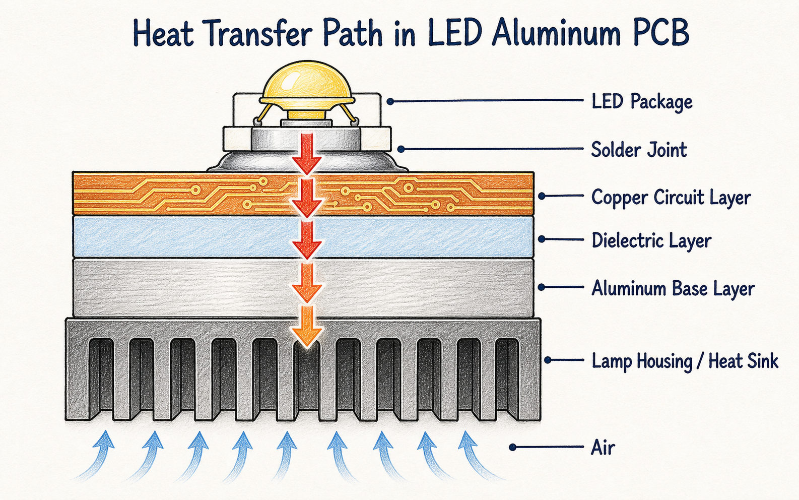 Heat must travel through the complete board and fixture path—not just reach the aluminum base.
Here is how we usually explain it:
- copper and aluminum help you move heat sideways once it arrives
- the dielectric is the thin layer heat must cross to reach the aluminum
- TIM and mounting quality decide whether the aluminum can hand that heat off cleanly
Your aluminum base is usually a spreader and a mechanical path into the fixture.
It is not automatically the biggest thermal resistance inside the board.
If your external path is weak—air gap, poor contact, undersized housing—the board upgrade alone will not save you.
The PCB is only one segment of junction-to-ambient.
Why the Dielectric Layer Is Often the Bottleneck
This is the part capability pages often skip when they talk to you.
Heat has to cross the dielectric before it reaches the aluminum base.
That layer has to do two jobs for you at once:
- move heat
- keep copper electrically insulated from the metal base
So it is thin, but it is not metal.
In a simple flat-layer model, thermal resistance goes up with thickness and down with thermal conductivity and area.
That is why IMS datasheets talk about dielectric thickness, thermal conductivity, and thermal impedance together.
They belong in the same discussion.
Weidmüller’s IMS guidance is a good example: insulation thickness often sits around 0.05–0.20 mm, with several thermal-conductivity grades in the market.
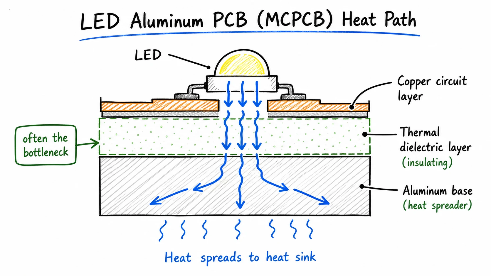 The dielectric is thin, but heat still has to cross it before the aluminum base can spread that heat toward the housing.
Use those numbers as orientation.
Do not treat them as proof that your project needs the top grade.
| Lever | What it usually does for you | What you should watch |
|---|---|---|
| Higher dielectric thermal conductivity (k) | Lowers through-plane thermal resistance | Cost and grade availability |
| Thinner dielectric | Lowers thermal resistance | Insulation / hi-pot margin |
| Larger copper / heat area | Helps for a given path | Layout density limits |
If you only ask “how thick is the aluminum?” you are missing half the board conversation.
Ask about the dielectric class and thickness too.
For many LED lighting boards we see, “right enough” dielectric beats “highest W/m·K on the brochure.”
If you want the material-side deep dive, start with our notes on aluminum PCB dielectric.
Board Specs You Can Control
You cannot rewrite physics on a quote form.
You can control the choices that show up on your drawing.
| Spec | Why it matters to you | Mass-production note |
|---|---|---|
| Dielectric k / thickness | Through-plane board resistance + insulation | Balance it. Do not max by default. |
| Aluminum base | Spreading and the mechanical path into the housing | Match your mounting design |
| Copper thickness / area | Lateral spreading and current | Size to layout, not to marketing |
| LED layout density | Hotspots and heat sharing | Often missing from “aluminum PCB, high thermal” emails |
From our side, the useful conversation with you is simple:
What power sits on the board?
How dense is the LED layout?
What does the board mount to?
What insulation margin do you need?
Then we choose stackup with you.
Not the other way around.
Copper still matters for current and lateral spreading.
It is not the main vertical heat path by itself.
If copper thickness is already on your drawing, we produce to that.
If you are still deciding, read how to choose aluminum PCB copper thickness for LED lighting before you default to thicker foil “for better cooling.”
For standard aluminum PCB fabrication for LED lighting, a practical stackup usually beats a capability-page shopping cart.
Is Higher Dielectric Thermal Conductivity Always Better?
No.
If you raise dielectric thermal conductivity, you usually help heat flow through the board.
That does not make it the best buy for every commercial lighting SKU you run.
Material suppliers publish multiple grades and thicknesses for a reason.
When we select with you, it is a trade study:
- thermal need
- insulation need
- process stability
- cost
- whether you can buy the same material again next month
A practical rule we use for volume lighting:
Use a higher-k dielectric when your design is near its thermal limit after layout and mounting make sense.
If your board already has margin, paying for the top grade may only raise your cost or sourcing risk.
| Situation | Higher-k more useful for you? | Prefer a practical grade? |
|---|---|---|
| Near Tj limit, dense high-power LEDs | Often yes | Only after layout and mounting are checked |
| Moderate power, good housing path | Rarely your first move | Usually yes |
| Cost-sensitive repeat lighting SKU | Only if you have proven need | Default starting point |
Also remember: the dielectric is one segment of your path.
Package, copper layout, TIM, and housing still sit in the same chain.
Buying a hotter material number will not fix a bad mounting interface. Jumping from aluminum PCB to copper PCB has the same problem if the dielectric or housing is still the limit.
If you want to see the real numbers on your specific layout before locking a material spec, run your LED count and dimensions through our free LED Junction Temperature Calculator. It compares volume 0.7 W/m·K boards with 1.0 commercial and 2.0 market grades side-by-side.
TIM, Mounting, and Secondary Heatsinks
This is where a “good board” can still run hot in your lamp.
The contact between the aluminum PCB backside and your housing / heatsink has its own thermal resistance.
If that interface is full of air gaps, heat stalls.
TIM is there to replace trapped air with a more conductive, conforming layer.
But TIM only helps you if:
- the surfaces are reasonably flat and clean
- the bond line is controlled
- mounting pressure is even enough to keep contact
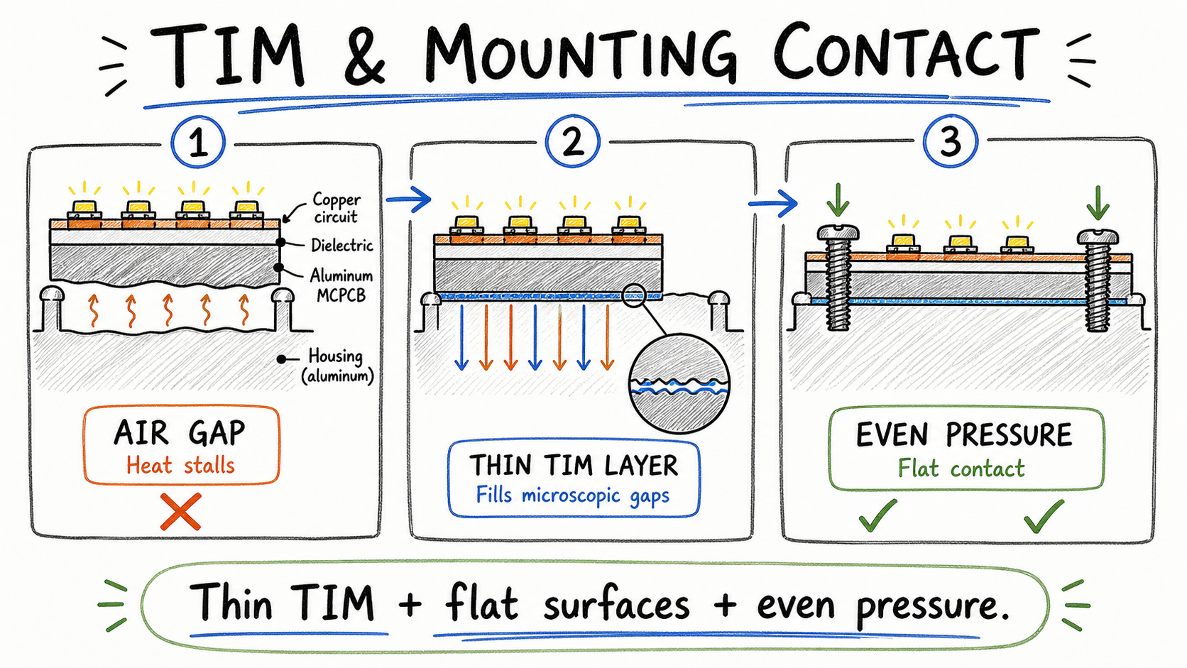 Thin TIM, flat mating surfaces, and even pressure help the aluminum base hand heat off to the housing.
Uneven screws, warped mating faces, or a dry gap can waste a carefully chosen dielectric.
One more honest line from our side:
An aluminum PCB does not automatically replace a heatsink.
In higher-power or dense LED designs, your housing, fins, or other secondary path still has to reject heat to ambient.
If you also need board-level assembly, contact quality after SMT assembly for LED aluminum PCB matters too.
A clean thermal pad on the drawing still has to sit flat in the real fixture.
Do Thermal Vias Work the Same Way on Aluminum PCBs?
Short answer for you: not in the FR-4 way.
On many FR-4 or multilayer boards, thermal vias under an LED thermal pad can help you move heat into deeper copper or a backside path.
Cree’s PCB thermal note shows that via arrays can help on FR-4 boards.
On a true single-sided aluminum PCB, the main heat path is already meant to go straight down through the dielectric into the metal base.
There is no multilayer FR-4 “bridge” for the via field to create in the same way.
So vias are usually not the first thermal lever on single-sided LED aluminum boards we build.
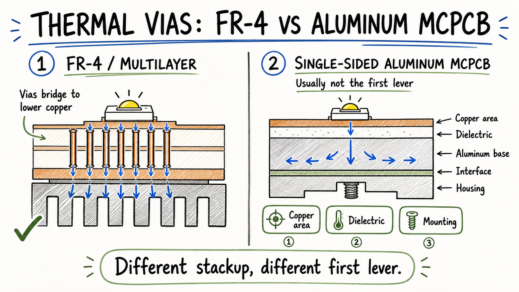 Thermal vias can bridge FR-4 layers, while a single-sided aluminum MCPCB already sends heat through its dielectric into the metal base.
| Board type | Thermal vias usually… | What you should work on first |
|---|---|---|
| FR-4 / multilayer | Often helpful under thermal pads | Via field + copper planes |
| Single-sided aluminum / MCPCB | Limited / nonessential for the main path | Dielectric + aluminum base + TIM / mounting |
If someone pastes an FR-4 via recipe onto your aluminum LED board, pause.
Check dielectric, copper area, and mounting first.
Practical Recommendation for LED Mass Production
If you are building volume LED lighting, we would use this order with you:
- Confirm single-sided aluminum PCB fits your product’s cost and thermal window.
- Size dielectric for heat and insulation—not max k by default.
- Keep copper thickness and copper area practical for current and spreading.
- Design the mounting path: flat contact, TIM if needed, even pressure, housing as a real heat path.
- Only then upgrade dielectric grade, copper, or secondary cooling if the board is still near its limit.
- Prefer a stackup you can repeat on the next order.
Capability menus list options.
Your mass production needs a practical build.
If you want a factory recommendation, you do not need a ten-page thermal report to start a conversation with us.
Send the drawing, LED power or current, and how the board mounts in the lamp.
That is enough for us to talk through a realistic single-sided aluminum stackup with you.
Conclusion
If you remember one thing, remember this:
LED aluminum PCB heat dissipation is a path problem.
In short: junction → copper → dielectric → aluminum base → interface → housing → air.
(Same idea as the fuller path at the top—package, solder, and TIM sit inside that chain.)
Get the dielectric and the mounting contact right before you chase the highest thermal-conductivity label.
And do not treat FR-4 via habits as automatic aluminum-board rules.
If you are building LED lighting boards for sample or bulk production, send us your drawing, power level, mounting method, and quantity.
We can help you check a practical single-sided aluminum PCB option for mass production—without defaulting to the highest W/m·K on the menu.
Need a quotation?
Send Gerber files and basic specifications. We reply within 1 business day.
Ask for Quote