LED PCB vs Aluminum PCB: Is There a Difference? (Buyer's Guide)

On This Page (Table of Contents)
Yes, there is a real difference.
LED PCB describes what the board does. It can be made from FR4, aluminum, copper, or ceramic.
Aluminum PCB describes what the board is made of. It is a metal-backed board built to pull heat away from LEDs.
Buyers mix these two terms up all the time. Most commercial lights run on aluminum boards, so people use "LED PCB" as a casual shortcut.
That shortcut causes real trouble on purchase orders.
If your RFQ only asks to "quote 5,000 pcs LED PCB", suppliers have to guess:
- One quotes cheap FR4 fiberglass.
- Another quotes bare aluminum.
- A third quotes a finished board with LEDs already mounted.
None of those quotes match. You lose two weeks just sorting out what is being priced.
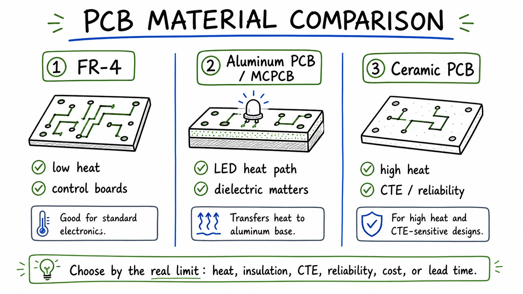 LED PCB describes what the board does, while aluminum MCPCB is one specific metal-backed substrate engineered for high heat transfer.
The Sourcing Ambiguity: Why "LED PCB" Is Not a Material Name
Calling a board an "LED PCB" tells the shop floor what the board does. It does not tell us what material to cut.
Industry standards make this exact distinction. In IPC-6012F (Qualification and Performance Specification for Rigid Printed Boards), metal-core boards (IMS) are classified as a rigid-board construction type, right alongside standard FR4. IPC does not recognize "LED PCB" as a material specification.
In our workshop, we separate every circuit board into three distinct buckets:
- Application (What it does): An LED board, a driver board, or a sensor board.
- Material (What it is made of): Standard FR4, single-sided aluminum PCB, or copper-core.
- Scope (What goes in the box): A bare unpopulated board, or a fully assembled module with parts mounted.
These three things are completely independent.
An LED board can use FR4. It can also use aluminum. Both are "LED PCBs," but their heat limits, shop routing, and costs are completely different.
In lighting hubs like Zhongshan, factories default to aluminum boards for downlights and high bays. That works fine on the phone. On a formal purchase order, it creates expensive mistakes.
Cross-Sectional Stackup & The "0.6–0.8 W/m·K" Thermal Reality
Where does the heat bottleneck actually live? Not in the aluminum base plate. It lives in the thin dielectric layer between the copper traces and the metal base.
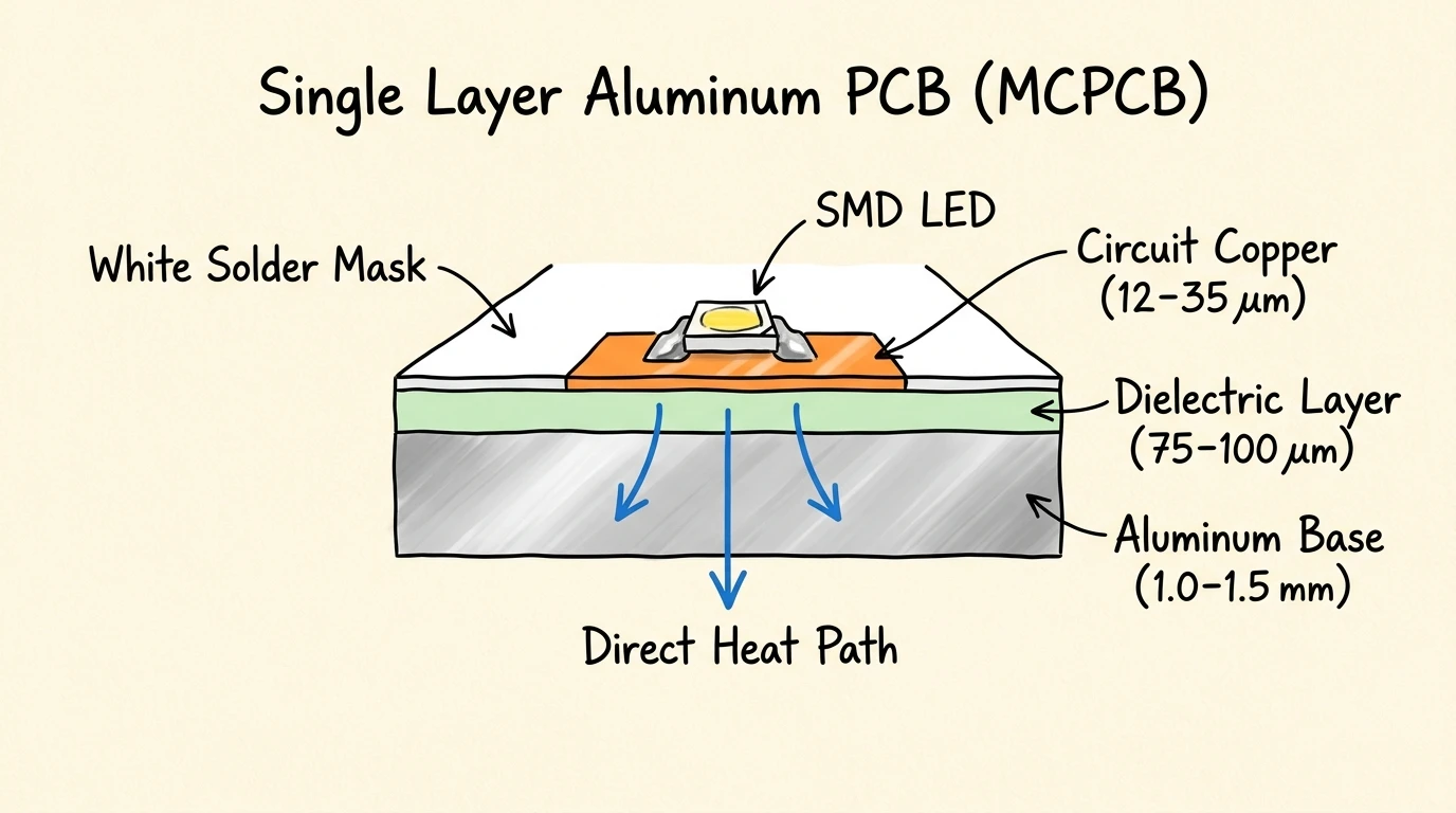 Heat from the LED die conducts through the copper pad and the dielectric layer before spreading laterally into the aluminum base.
Standard 2-layer FR4 uses epoxy resin and woven glass cloth. Standard FR4 epoxy has a thermal conductivity of roughly 0.3 W/m·K. That is essentially an insulator. Heat from the LED gets trapped right on the top copper foil.
A single-layer aluminum board (IMS) uses three bonded layers:
- Top copper circuit foil (12 µm to 70 µm)
- Ceramic-filled dielectric layer (75 µm to 150 µm)
- Solid aluminum base plate (1.0 mm to 1.6 mm)
The dielectric layer has two jobs. It stops circuit voltage from shorting into the aluminum plate, and it transfers heat straight down into the metal base.
The Zhongshan Market Reality: The 0.6–0.8 W/m·K Tier
Most online guides say aluminum boards start at 1.0 W/m·K or 2.0 W/m·K.
In China's lighting markets, that is only half the truth.
To hit rock-bottom prices on residential bulbs and ceiling fixtures, raw material suppliers run massive batches of 0.6 to 0.8 W/m·K laminate. These boards use unreinforced resin with minimal ceramic filler. They pass basic 1000V hipot tests and survive 270°C solder floats. For a 5-watt residential bulb, they work fine.
The trap catches overseas buyers.
If you write "aluminum PCB" on an RFQ for commercial high bays, suppliers competing on price will quote this 0.6 to 0.8 W/m·K stock. Your fixture will run 15°C to 25°C hotter than your thermal simulations.
Export fixtures requiring CE or UL marks need verified commercial material. Global laminate makers establish this baseline with standardized datasheets, such as Ventec's VT-4B1 (1.0 W/m·K) and VT-4A1 (1.6 W/m·K).
In third-party CNAS laboratory testing (Microtek Report No. 46724, tested per ASTM D5470), a certified 1.0 W/m·K laminate delivers 0.98 W/m·K at the dielectric, with 6.16 kV breakdown strength. That difference determines whether your fixture passes customer audits or overheats in the field.
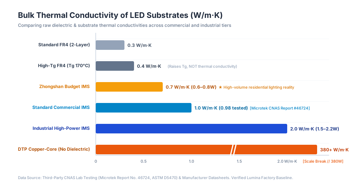 Bulk thermal conductivity across common LED substrates, highlighting the practical 0.6–0.8 W/m·K Zhongshan commercial tier.
What About High-Tg FR4?
Hardware engineers often specify High-Tg FR4 (such as Tg 170°C material) to stop LED overheating.
This does not solve the heat problem.
Tg measures glass transition temperature. It tells you when the epoxy begins to soften. Raising Tg stops the board from blistering, but it does not pull heat away.
Official datasheets confirm this limit. For example, the Isola 370HR datasheet (an industry-standard high-Tg laminate) reports a thermal conductivity of just 0.40 W/m·K tested per ASTM E1952.
Heat stays locked inside the LED pad, baking the phosphor and shortening diode life.
| Substrate Category | Verified Thermal Conductivity | Dielectric Construction | Typical Breakdown Isolation | Primary Application | Relative Cost Index |
|---|---|---|---|---|---|
| Standard FR4 (2-Layer) | 0.25 - 0.35 W/m·K | Woven E-glass + Epoxy | 15 - 20 kV/mm | Indicators, loose low-power strips (<= 0.2W/LED) | 1.0x (Baseline) |
| High-Tg FR4 (Tg 170°C) | 0.35 - 0.40 W/m·K | Modified epoxy core | 18 - 22 kV/mm | Power drivers, industrial control logic | 1.2x – 1.4x |
| Budget IMS (Zhongshan Tier) | 0.6 - 0.8 W/m·K | Low-filler epoxy dielectric | 1.0 - 1.5 kV AC | Residential bulbs, budget ceiling modules | 1.1x – 1.3x |
| Commercial Standard IMS | 1.0 W/m·K (0.98 tested) | Ceramic-filled polymer (Microtek #46724) | >= 6.16 kV AC | Commercial downlights, troffers, panel lights | 1.4x – 1.6x |
| Industrial High-Power IMS | 1.5 - 2.2 W/m·K | High-filler prepreg (Ventec VT-4A1) | >= 4.0 kV AC | High-bay lighting, street lamps, stage fixtures | 1.8x – 2.4x |
| Direct Thermal Path (DTP) Copper | >380 W/m·K (Pad) | Zero dielectric beneath thermal pad | Direct metal contact | Automotive headlights, UV curing (>10 W/cm²) | 4.0x – 6.0x |
The Engineering Decision Boundary: When Can You Use FR4 vs. Mandatory Aluminum?
Choosing between FR4 and aluminum comes down to two numbers: emitter power and surface power density.
LEDs turn only 30% to 40% of electrical energy into light. The rest turns into heat. All that heat concentrates inside a die measuring just a few square millimeters.
Under IES LM-80 testing standards and IES TM-21-11 lifetime projections, keeping junction temperatures (Tj) low is vital. Once junction temperature tops 85°C, lumens drop fast, chromaticity drifts off spec, and operating life drops by up to 50%.
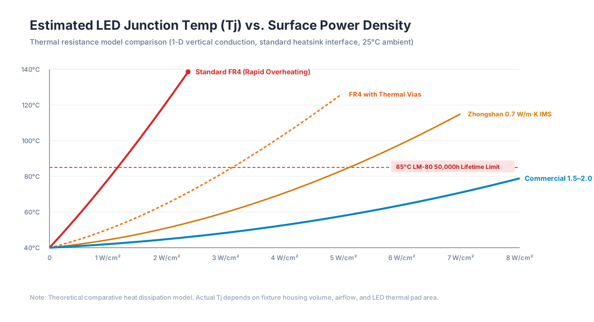 Estimated LED junction temperature versus board power density, comparing FR4, thermal vias, and aluminum substrates against the 85°C LM-80 lifetime threshold.
When FR4 Works Fine
You can safely stay with FR4 when:
- Emitter power is under 0.2W. Low-power indicator boards and loose decorative strips make very little heat.
- Component spacing is wide. Heat escapes into surrounding air before hot spots form.
- Duty cycles are short. The light does not run 24 hours a day.
When Aluminum Is Mandatory
You must switch to aluminum when:
- Mid-power emitters sit in tight rows. Boards using SMD 2835 or 3030 chips driven at 0.5W to 1.5W per piece.
- Power density tops 10 W/dm². Natural air convection cannot clear heat from FR4 traces fast enough.
- Fixtures are sealed. Recessed downlight cans and vapor-tight outdoor fittings offer zero airflow.
- You offer a 5-year warranty. Keeping junction temperatures below 75°C is the only way to reach 50,000-hour lifespans.
Can Thermal Vias Save an FR4 Board?
Engineers often ask: "Can I just drill lots of thermal vias into an FR4 board?"
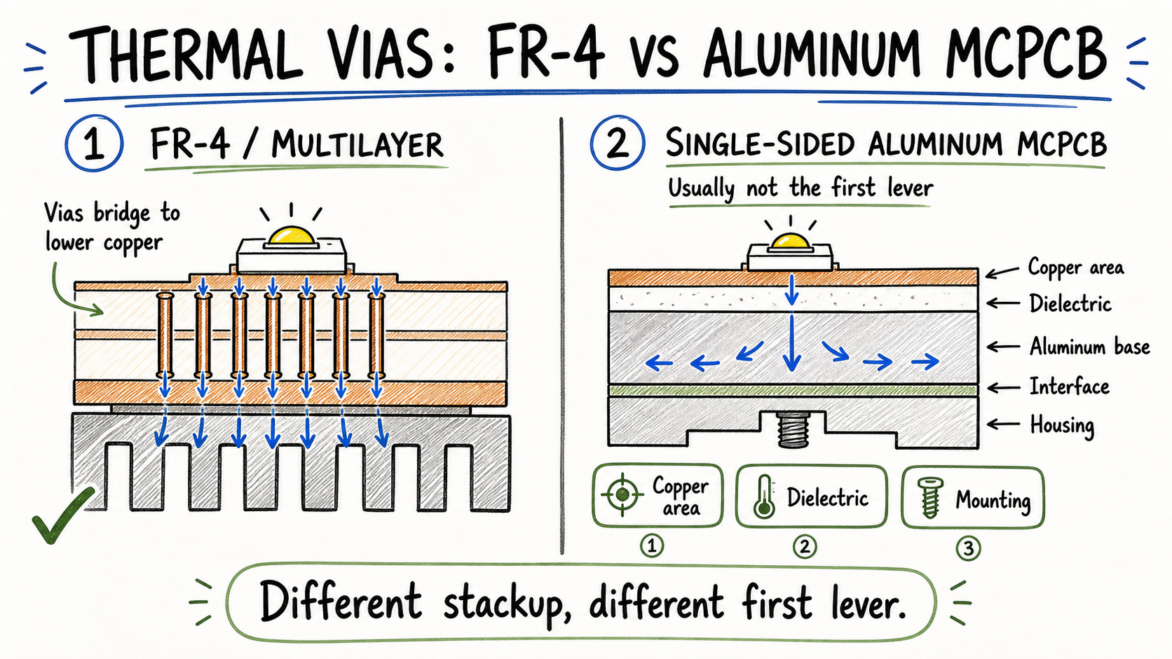 Plated thermal vias help conduct heat to the bottom copper of an FR4 board, but heat flow remains constrained by thin barrel walls compared to solid 1-D aluminum conduction.
Thermal vias help, but they run into two hard limits:
First, heat has to travel through thin copper plating (usually 20 to 25 µm). Even dozens of vias leave higher thermal resistance than a basic aluminum dielectric layer.
Second, drilling hundreds of tiny holes wears out drill bits and adds plating time. In production runs, an FR4 board full of thermal vias often costs more than a standard single-layer aluminum board.
The Manufacturing Trap: Why Single-Layer Aluminum PCBs Cannot Use Through-Hole (THT) Parts
One common design error on new customer Gerbers is adding through-hole (THT) components to a single-layer aluminum board.
Standard single-layer aluminum boards cannot use through-hole pins.
The reason is simple: the aluminum base plate is solid conductive metal.
If a drill punches through copper, dielectric, and aluminum, the hole wall exposes bare metal. Insert a leaded wire or pin into that hole, and it touches the aluminum base. The moment power turns on, you get an instant short circuit.
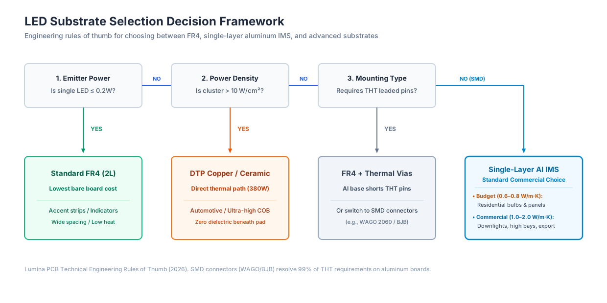 Decision framework for selecting between FR4, aluminum MCPCB, and advanced copper substrates based on power, density, and component mounting constraints.
How Real Fixtures Handle Wire Connections
Because single-layer aluminum boards are surface-mount only, factories use three reliable wire connections:
- Surface-mount push-in terminal blocks. Parts like WAGO 2060 or BJB 46.111 sit flat on top copper pads. They go through reflow ovens alongside your LEDs. On the assembly line, workers just strip wires and push them in.
- Direct wire soldering. Wires solder flat against copper pads at the board edge. If you do this, always add strain relief (silicone glue or a wire clamp). Without strain relief, a sharp pull can rip the copper pad right off the board.
- Non-plated pass-through routing (NPTH). If DC wires come from a rear driver box, we rout a wide clearance slot with no copper rim. Wires pass cleanly through the slot and solder to top-side pads.
Watch Your Edge Clearances
The aluminum base plate often touches the luminaire housing, so electrical isolation rules are strict. To satisfy safety standards like IEC 60598-1 for luminaires and UL 8750 for LED equipment, mains-voltage LED modules must pass 1500V to 3000V AC Hi-Pot breakdown tests.
Follow IPC-2221B creepage and clearance rules during layout:
- Keep copper traces at least 0.8 mm to 1.0 mm away from routed board edges and V-cut grooves.
- Keep copper pads at least 1.5 mm away from screw heads. A torqued screw head can bite through solder mask and short to the aluminum plate.
The Secondary Sourcing Trap: Bare Board PCB vs. Turnkey PCBA (The 3.50 Shock)
Quotation surprises happen when an RFQ asks for an "LED PCB" without stating procurement scope.
- A $0.85 quote covers a bare circuit board (PCB): etched copper, dielectric, aluminum plate, and solder mask.
- A $3.50 quote covers a turnkey assembled board (PCBA): the bare board, brand-name LEDs, resistors, connectors, SMT placement, reflow soldering, and 100% lighting tests.
If a buyer approves a $0.85 quote expecting assembled light engines, the project loses a month waiting to source parts and schedule SMT lines.
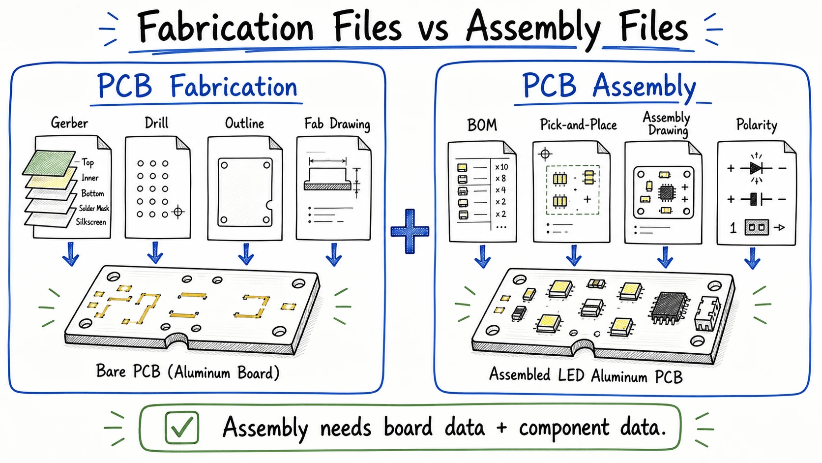 Procuring bare boards requires only Gerber manufacturing files, while turnkey SMT assembly requires a matched BOM and centroid coordinate files.
State your deliverable scope in your initial RFQ:
| Requirement Scope | Deliverable | What the Factory Supplies | What You Send to the Factory |
|---|---|---|---|
| Bare Board Fabrication | Unpopulated bare boards | Raw aluminum laminate, etched copper, white mask, HASL/OSP finish, V-scoring | Gerber files (.GTL, .GTS, .GTO, .GKO) and fabrication drawing |
| Turnkey LED PCB Assembly | Ready-to-install light engines | Bare board + all BOM components (LEDs, resistors, WAGO connectors) + SMT assembly + testing | Gerbers + detailed BOM with LED binning/CCT + Centroid (.XY) placement file |
Total Cost of Ownership: Bare-Board Price Is Not the System Thermal Cost
When purchasing managers compare invoices, FR4 almost always shows a lower bare-board price.
Looking only at the PCB price is a common mistake.
Heat has to go somewhere. If you put a 30W LED array on an FR4 board to save $0.80, that board will quickly overheat.
To keep the LEDs alive, your team now has to add:
- An extruded aluminum heat sink (+$2.50)
- A thermal interface pad (+$0.60)
- Screws and extra manual labor (+$0.80)
That creates **0.80 on the bare board.
An aluminum board serves as its own heat spreader. In standard downlights, the board fastens straight against the fixture housing with two screws. No external heatsinks. No messy thermal paste.
The bare board costs 2.00.
The Optical Value of White Solder Mask
Thermal performance is not the only metric that affects your bill of materials. Optical reflection matters too.
Standard industrial boards use green or black solder mask. Those dark colors absorb 10% to 20% of emitted light.
Commercial LED boards use specialized high-reflectivity white solder mask with reflectance ratings above 85% to 90%. Inside a fixture cup or diffuser lens, that white surface bounces lumens back out into the room.
That 3% to 5% boost in luminaire optical efficiency lets engineers back off drive currents slightly, lowering heat without losing visible brightness.
Sulfur-Free Oxidation
Another shop-floor issue that affects LED reliability is sulfur residue on the raw aluminum plate.
If aluminum sheets go through low-cost chemical oxidation baths containing sulfur, chemical residues cling to the metal backing.
When the board enters a 250°C reflow oven during SMT assembly, that residual sulfur vaporizes. Sulfur gas attacks the silver plating in LED reflector cups, turning emitters yellow or black within a few hundred hours.
Specifying sulfur-free oxidized aluminum plates removes this failure mode completely.
The Practical RFQ Specification Checklist: How to Order Without Guesswork
To get fast, accurate quotes without engineering delays, include these seven parameters in your fabrication notes:
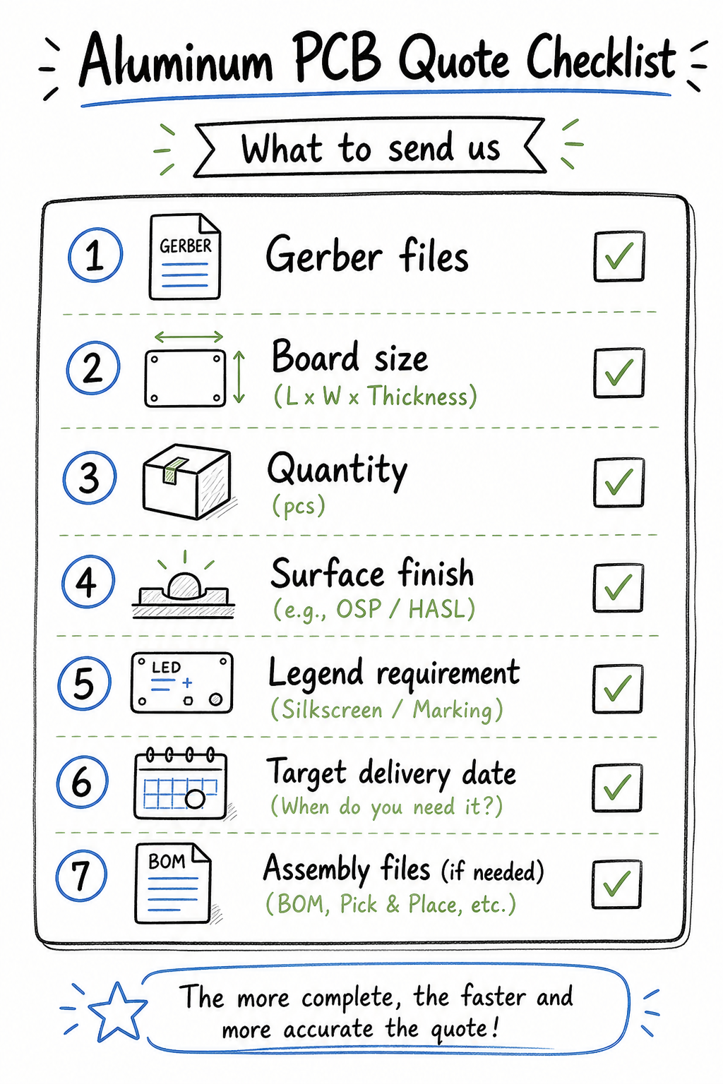 A structured checklist ensures quotation drawings cover material grade, copper weight, thermal conductivity, and assembly scope upfront.
- Substrate family: Specify standard FR4, 1-layer aluminum IMS, or copper-core.
- Aluminum alloy: Choose 5052-H32 for maximum flatness after SMT, or 1060 for budget stamping.
- Board thickness: Standard options are 1.0 mm, 1.2 mm, or 1.6 mm (1.6 mm is the commercial standard).
- Finished copper weight:
- 1 oz (35 µm) is the standard for general lighting.
- 12 µm (1/3 oz) works well for low-current series strings.
- 2 oz (70 µm) is recommended when currents exceed 3A to avoid trace heating (read our guide on aluminum PCB copper thickness options).
- Verified dielectric conductivity:
- Specify >= 1.0 W/m·K for commercial downlights, panels, and tubes.
- Specify 1.5 to 2.0 W/m·K for high-power industrial fixtures.
- State your required Hi-Pot test voltage (such as 3000V AC / 60s).
- Solder mask and finish: Specify high-reflectivity White solder mask, paired with Lead-Free HASL or OSP.
- Procurement scope: State clearly: "Bare PCB Only" or "Turnkey SMT Assembly." If turnkey, attach a complete BOM with LED part numbers, CCT, and minimum CRI.
Final Technical Takeaway
"LED PCB" describes what a circuit board does. "Aluminum PCB" describes how that board manages heat.
If you build low-power indicator boards where LEDs run below 0.2W, standard FR4 is the economical choice. The moment your luminaire packs mid-power or high-power surface-mount LEDs into closed housings, single-sided aluminum PCB is necessary to keep junction temperatures under 85°C. To check whether your layout stays safely under 85°C before freezing your substrate choice, test your exact dimensions with our free LED Junction Temperature Calculator.
When sending RFQ files to Lumina PCB, specify your alloy grade, dielectric thermal rating, finished copper weight, and deliverable scope upfront. Nailing down those four specifications eliminates quotation mismatches and gets production-ready samples into your testing fixtures days faster.
Need a quotation?
Send Gerber files and basic specifications. We reply within 1 business day.
Ask for Quote