Aluminum PCB Board Guide for LED and Power Applications

On This Page
Aluminum PCB Board Guide for LED and Power Applications
An aluminum PCB is a metal-core board built to move heat away from your components.
It also supports your circuit mechanically.
And it is the industry standard for LED lighting, power supplies, automotive lamps, and motor drives.
Let's look at how they work, how they compare to FR-4, and how to specify the right board stack for your project.
1. How an Aluminum PCB Is Built
A typical aluminum PCB is made of three functional layers bonded together:
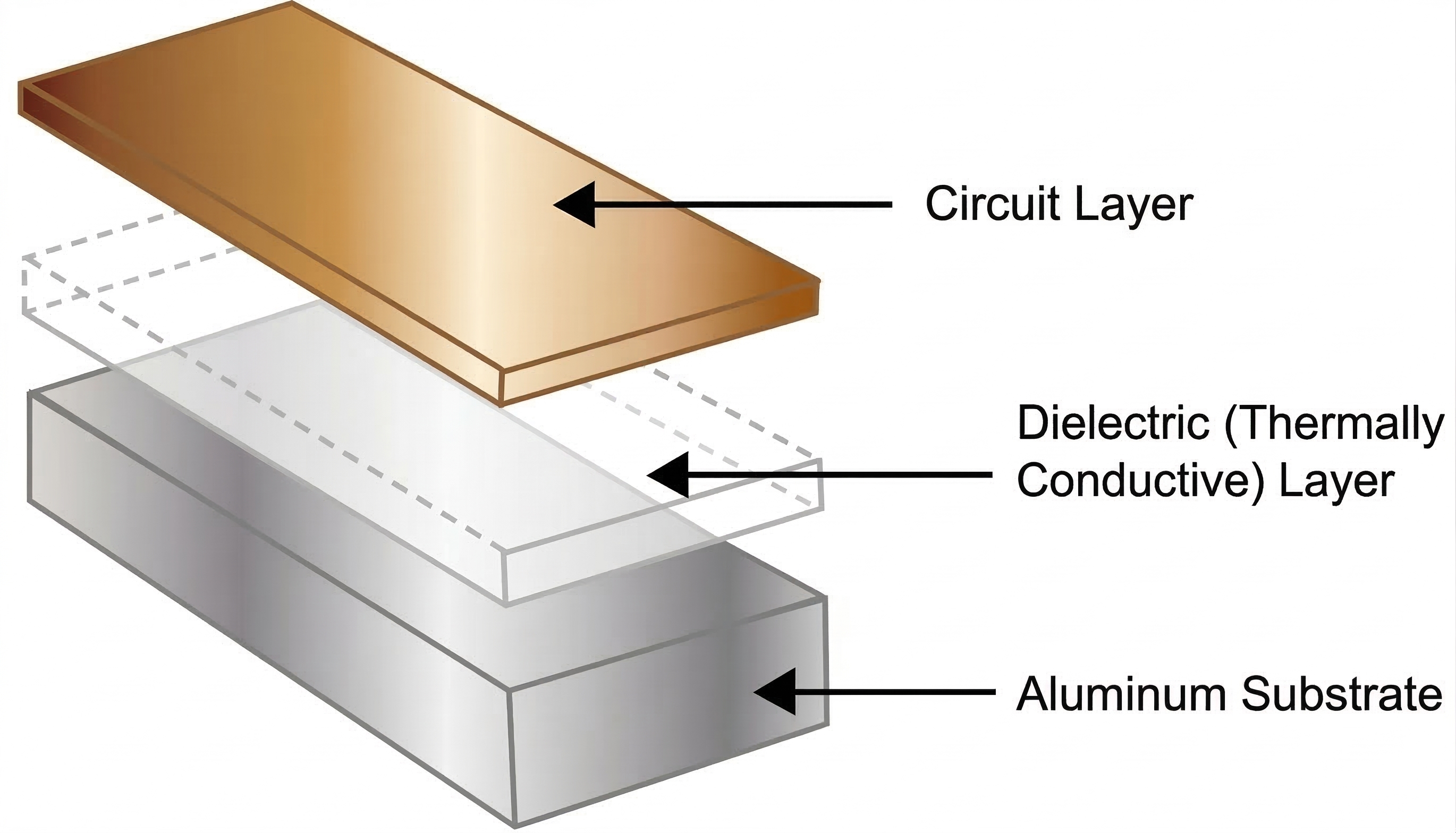
Copper Circuit Layer
The top copper layer forms your traces and component pads.
While standard designs use 1 oz copper, high-power circuits often specify 2 oz or 3 oz copper.
This helps handle larger currents and spreads heat laterally across the board.
But keep in mind: heavier copper is only a partial fix.
It cannot replace a highly conductive path down into the substrate.
Dielectric Insulation Layer
The dielectric layer sits between the copper circuit and the aluminum base.
This is the most critical part of the stackup.
Why?
Because it has to perform two conflicting jobs at the same time:
It must provide electrical insulation while allowing heat to pass through.
In practice, the dielectric layer is usually the thermal bottleneck.
Aluminum base plates conduct heat exceptionally well. But the total thermal performance of the board depends on the dielectric's thickness and thermal conductivity (measured in W/m·K).
If you use a cheap, low-conductivity dielectric, your components will run hot — no matter how thick your aluminum base is.
Aluminum Base Layer
The aluminum base provides structural rigidity and acts as a heat spreader.
By distributing heat across a larger surface area, it prevents localized hot spots.
This metal backing also resists warping.
That is vital for long LED linear boards exposed to mechanical vibration and thermal expansion cycles.
Depending on the operating environment, the backside of the aluminum base can receive a protective finish to prevent corrosion and oxidation.
This is especially important in outdoor or industrial applications.
2. Aluminum PCB vs. FR-4
FR-4 is the default material for the vast majority of electronics.
But when heat dissipation is your primary requirement, aluminum PCBs are the reliable choice.
Here is a quick comparison:
| Comparison Point | Aluminum PCB | FR-4 PCB |
|---|---|---|
| Thermal Conductivity | High (1.0 to 9.0+ W/m·K) | Low (approx. 0.25 W/m·K) |
| Heat Dissipation | Direct downward path to heatsink | Limited; requires thermal vias or fans |
| Rigidity & Warp | Excellent; rigid metal backing | Flexible; prone to warping under heat |
| Routing Options | Mostly single-sided | Multilayer (2, 4, 10+ layers) |
| Electrical Insulation | Relies entirely on the dielectric layer | Base material itself is non-conductive |
| Average Cost | Higher | Lower |
Thermal Performance
FR-4 has a thermal conductivity of around 0.25 W/m·K.
Aluminum PCBs start at 1.0 W/m·K and can go up to 9.0 W/m·K or higher.
This direct thermal path is critical for LEDs.
Operating temperature directly impacts light output, color shift, and lifespan.
Mechanical Stability
FR-4 boards are flexible and can warp under thermal stress or vibration.
Aluminum PCBs provide a rigid metal base that resists bending.
This makes them ideal for long LED linear fixtures, automotive headlights, and industrial power assemblies.
Electrical Insulation
Because FR-4 is fiberglass, it is inherently non-conductive.
Aluminum is a conductor.
This means electrical isolation depends entirely on the dielectric layer.
If your design operates at high voltages, you must specify a dielectric thickness that can withstand the required breakdown voltage.
Design Flexibility
This is FR-4's primary advantage.
You can easily design multi-layer FR-4 boards with complex internal signal routing, microvias, and fine-pitch components.
Aluminum PCBs are mostly restricted to single-sided layouts.
Creating multi-layer or double-sided aluminum PCBs requires complex, expensive machining.
This makes them impractical for dense digital circuits.
3. Common Applications
Single-sided aluminum PCBs are the most common structure in production.
They feature components on the top copper layer and an exposed aluminum base on the bottom.
This layout keeps manufacturing costs low while maximizing heat transfer.
You will find aluminum PCBs in:
- LED Lighting: Downlights, streetlights, architectural wall washers, and automotive headlights.
- Power Supplies: DC-DC converters, rectifiers, and power modules.
- Motor Controls: Industrial servo drives and automotive motor controllers.
While double-sided or multi-layer aluminum PCBs exist, they are complex to manufacture.
They also carry a significant cost premium.
For most projects, staying with a single-sided metal core board is the most cost-effective path.
4. Pros and Cons of Aluminum PCBs
Advantages
- Superior Thermal Transfer: Dramatically lowers operating temperatures for high-power components.
- High Rigidity: Prevents thin, long PCBs from flexing or warping under heat or mechanical stress.
- Reduced System Size: Often eliminates the need for bulky heatsinks, fans, or large enclosures.
Limitations
- Higher Board Cost: Raw materials and specialized lamination make them more expensive than standard FR-4.
- Routing Limitations: Virtually locks your design into a single-sided layout.
- Soldering Difficulty: Because the board dissipates heat so quickly, hand-soldering and SMT reflow require carefully adjusted thermal profiles to ensure proper solder joints.
5. Key Factors Influencing Thermal Performance
When designing or sourcing aluminum boards, keep these three factors in mind:
The Dielectric is the Gatekeeper
Many designers focus on the thickness of the aluminum base.
But the dielectric layer is the primary thermal bottleneck.
A 1.5mm aluminum base conducts heat beautifully. But if it is paired with a thick, low-conductivity dielectric, the heat will remain trapped in the copper layer.
Always specify both the dielectric’s thickness (typically 75–100 μm) and its thermal conductivity (e.g., 1.5 W/m·K to 3.0 W/m·K).
Copper Weight and Pad Layout
Heavier copper (2 oz or 3 oz) spreads heat laterally before it travels down through the dielectric.
Maximizing the copper area under and around hot components (like LED thermal pads) reduces localized thermal resistance.
Mounting and Interface Materials
An aluminum PCB cannot dissipate heat into thin air.
It must transfer it to an enclosure or heatsink.
If the board is not mounted completely flat against the heatsink, or if you do not use a high-quality thermal interface material (TIM) like thermal grease or pads, the air gaps will ruin the thermal path.
6. Practical Design Guidelines
If you are laying out an aluminum PCB, follow these guidelines to prevent manufacturing and thermal issues:
- Specify Clearance and Creepage: Because the aluminum base is conductive, keep a safe distance between your copper traces/pads and the board edge or mounting hole walls. A clearance of at least 1.0mm is standard to prevent high-voltage arcing.
- Optimize Thermal Pads: Ensure the component footprints match the manufacturer's recommended thermal pad layouts. Do not use thermal relief patterns on pads that need to dissipate heat directly into the board.
- Balance the Copper Distribution: Uneven copper distribution across the board can cause uneven heating during reflow, leading to board warp. Keep copper coverage as balanced as possible.
7. Manufacturing Considerations
While aluminum PCBs share imaging and etching steps with standard FR-4, the metal backing introduces unique fabrication steps:
- Lamination Quality: High-pressure lamination is required to bond the copper and dielectric to the aluminum base. If the bond is uneven, microscopic delamination can occur under thermal cycling, ruining the thermal path.
- Machining and Routing: Cutting, routing, and drilling metal requires specialized tooling. Poor burr control during routing can leave sharp metal shards along the board edges, which can short out traces or slice through the solder mask.
- Solder Mask Selection: For LED boards, specify a high-reflectivity white solder mask. Over time, heat and UV light from LEDs can cause standard white masks to turn yellow or brown, reducing reflectivity. Ensure your manufacturer uses a heat- and UV-resistant solder mask formulation.
8. Cost Factors & Sourcing
The cost of an aluminum PCB is driven by:
- Base Material Thickness: Standard thicknesses (1.0mm to 1.6mm) are highly cost-effective. Choosing non-standard thicknesses increases material costs.
- Dielectric Performance: Premium dielectrics with high thermal conductivity (3.0 W/m·K or higher) cost significantly more than standard 1.0 W/m·K materials.
- Outline Complexity: Rectangular boards are easy to panelize and cut. Complex shapes, interior slots, or heavy routing drive up fabrication costs.
| Cost Factor | Effect on Cost | Sourcing Tip |
|---|---|---|
| Aluminum Base Thickness | Thicker material increases cost | Stick to 1.0mm or 1.6mm standard baselines |
| Copper Thickness | Heavier copper (2 oz+) increases cost | Use 1 oz unless current exceeds 3A |
| Dielectric Thermal Rating | High-performance (3.0+ W/m·K) increases cost | Use 1.0 - 1.5 W/m·K unless simulation shows overheating |
| Board Outline | Irregular shapes, cutouts, and slots increase cost | Use rectangular shapes to maximize panel utilization |
| Surface Finish | Specialized finishes (ENIG) increase cost | OSP is the most economical; HASL is next |
Aluminum vs. Copper Core
For extreme thermal demands, copper-core boards (COB or direct thermal path) are available.
But they are heavy and expensive.
For most LED and power designs, aluminum provides the best balance of thermal transfer, weight, and manufacturing cost.
9. Sourcing Checklist
Before sending your files to a manufacturer for a quote, make sure you have specified:
- Aluminum Base Thickness: (e.g., 1.0mm, 1.6mm) and alloy type (typically 5052 or 1060).
- Copper Weight: (e.g., 1 oz, 2 oz).
- Dielectric Specifications: Thermal conductivity (W/m·K) and thickness.
- Surface Finish: OSP is the standard cost-effective finish; HASL or ENIG are options for long-term storage or high-reliability needs.
- Solder Mask: Typically high-reflectivity white for LED boards.
- Panelization Requirements: Specify if you want the boards supplied as individual pieces or in SMT-ready panels.
Summary
Choose aluminum PCBs when your design runs hot, features simple single-sided routing, and requires robust mechanical stability.
Choose FR-4 when you need multilayer routing, high signal density, and cost-efficiency, and your heat loads can be managed through standard air cooling or thermal vias.
If you are ready to prototype or source your next LED or power project, contact our engineering team. We can review your Gerber files and help you select the most reliable, cost-effective stackup for production.
Join Our Industrial Community
Get exclusive technical whitepapers and industry news delivered to your inbox every month. No spam, only professional insights.