BOM List for PCB Assembly: 7 Core Columns & Free Excel Template

On This Page (Table of Contents)
A vague BOM can delay your PCB assembly quote before a single component is ordered.
Take the description “2835 LED, 4000 K.”
It sounds specific. It is not enough to identify one orderable LED.
The assembler still needs to know:
- Which manufacturer makes the LED
- Which complete manufacturer part number (MPN) to order
- Which locations use it
- Whether bin limits apply
- Whether substitution is allowed
A usable BOM list for PCB assembly answers three questions without guesswork:
- What exact part goes on the board?
- How many are fitted on one PCBA?
- Which reference designators use that part?
Free Engineering Download: Save setup time by downloading our Lumina Standard LED PCB Assembly BOM Template (.xlsx) (also available as .csv). Pre-formatted with 7 core columns, LED binning rules, DNP syntax, and engineering checks to ensure fast RFQ turnaround.
There is no universal spreadsheet layout for every assembly provider. But the information above must be clear, and the BOM must agree with the released pick-and-place file and assembly drawing.
A PCB Assembly BOM Is More Than a Shopping List
A PCB assembly bill of materials is the controlled parts list for one PCBA revision and build variant.
Purchasing uses it to identify and order components. Production uses the reference designators to connect each component with locations such as D1, R7, or U2.
That relationship matters more than the appearance of the spreadsheet. IPC-2588, for example, describes BOM data through assemblies, part quantities, package information, and associated reference designators. It does not require every factory to use the same Excel template.
The BOM also does not replace your other assembly files.
| File | The question it answers |
|---|---|
| BOM | What parts are fitted, and how many go on one PCBA? |
| Pick-and-place file | Where does each SMT part go, on which side, and at what rotation? |
| Assembly drawing | How should polarity, orientation, DNP locations, and special notes be interpreted? |
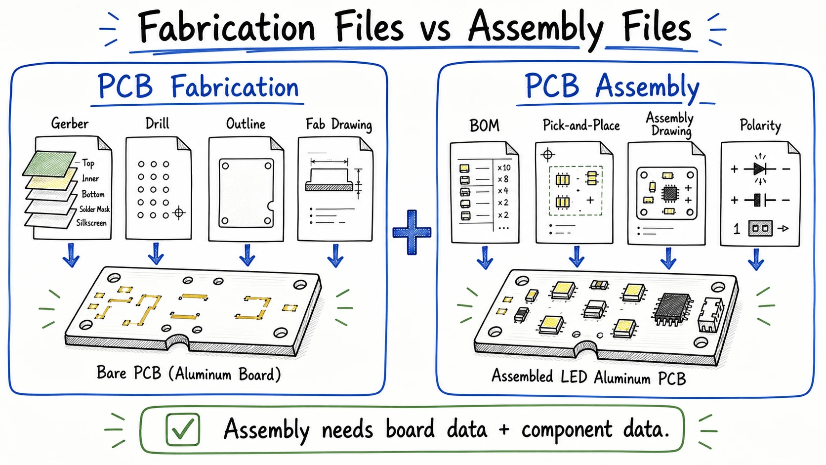 PCB assembly needs component data and placement instructions alongside the bare-board manufacturing files.
Altium's PCB assembly output guidance treats these as separate but connected production outputs. If you need the wider file package, see our guide to PCB files for manufacturing.
Use These Core BOM Columns First
Start with one row and ask a simple question:
Can the factory identify the part, count it for one finished board, and map it to every fitted location?
If the answer is yes, you have the core of a usable BOM. Add other columns only when they control sourcing, a build variant, or an assembly requirement.
| Priority | BOM column | What to enter | Why it matters |
|---|---|---|---|
| Core | Line or item number | One unique row number | Makes questions and revisions easier to track |
| Core | Reference designator | D1-D24, R3,R7, or U1 | Maps the part to PCB locations |
| Core | Qty per PCBA | Fitted count on one finished board | Prevents order or panel quantity from entering the BOM count |
| Core for controlled parts | Manufacturer | The actual component maker | Separates the maker from the distributor |
| Core for controlled parts | MPN | Complete manufacturer ordering code | Identifies the exact orderable component |
| Core | Description or value | Type, value, tolerance, rating, or key specification | Provides an engineering cross-check |
| Core | Package | 0603, SOT-23-3, or 2835 LED | Identifies the purchased physical form |
| Conditional | PCB footprint | Released CAD footprint name | Helps when the package name does not fully define the land pattern |
| Conditional | Mount and side | SMT, THT, or manual; top or bottom | Supports assembly review |
| Conditional | Population status | FIT, DNP, or DNI | Controls variant-specific locations |
| Conditional | Approved alternate | One exact approved alternate MPN | Prevents uncontrolled substitution |
| Conditional | Sourcing note | Customer supplied or assembler sourced | Assigns purchasing responsibility |
| Conditional | Build note | Binning, polarity, handling, or another instruction | Records a requirement that needs explicit control |
Use the assembler's template when one is supplied. For manual review and import, a clean XLSX or CSV is normally more useful than a PDF-only BOM. PCBWay's published BOM guidance, for example, requests Excel or CSV. That is a provider workflow, not an IPC rule.
Do generic passives always need an exact MPN?
Not always.
A row such as 10 kΩ, ±1%, 0603 may be enough when the resistor is genuinely generic and the assembler is authorized to select the brand. Once voltage, dielectric, rated power, compliance, or customer approval matters, list the manufacturer and complete MPN.
For LEDs, drivers, connectors, and other controlled parts, value plus package usually leaves too much open.
Get RefDes, Quantity, MPN, and Package Right
A BOM with 15 columns can still fail on four basic fields. Check these before you spend time polishing the spreadsheet.
1. Make every RefDes match the released PCB data
Use the exact designators from the released design.
If the PCB calls a component U2, do not rename it IC2 in the BOM. Identical components can share one row, but every fitted location must appear once.
- Clear: D1,D2,D3,D4,D5,D6
- Also clear when every position is fitted: D1-D24
- Avoid: D1-D24 except D13
A person may miss the exception, and import software may not interpret it correctly. List the fitted designators or split the row.
2. Make quantity mean quantity per PCBA
Use one rule throughout the file: Qty per PCBA must equal the number of fitted reference designators on that row.
If a row lists R1,R3,R7,R9, the quantity is 4.
It is not:
- The total quantity for the order
- The number of boards in a panel
- The reel quantity
- A purchasing allowance for setup loss
Those numbers belong in purchasing or production planning. The BOM describes one finished board.
3. Use the complete manufacturer part number
The manufacturer tells the factory who makes the component. The MPN tells purchasing which exact part to order.
Do not replace them with a distributor name or SKU. Keep distributor data in separate columns when the source must also be controlled.
And do not cut off the MPN suffix. That suffix may identify package, tolerance, voltage, grade, finish, or packing method.
An entry such as MPN-A / MPN-B / equivalent creates another decision for purchasing.
Use one primary MPN. Put exact, approved substitutes in a separate column or controlled list.
4. Do not confuse package with footprint
The package describes the component body you buy. The footprint describes the pads and assembly geometry on the PCB.
For a standard passive, 0603 may be enough after the component and land pattern have been checked. For an LED, connector, or exposed-pad device, the nominal package name may not settle the question.
Two LEDs can both be sold as 2835 and still differ in pad geometry, polarity marks, optical construction, or recommended solder pattern. Check the exact MPN against the released footprint instead of assuming the shared package name makes them interchangeable.
Treat DNP as a Release Decision
DNP means Do Not Populate. DNI means Do Not Install.
In normal PCBA use, both mean the footprint exists on the PCB, but the location must remain empty for the named revision or variant.
| RefDes | Qty per PCBA | Status | Description | Build note |
|---|---|---|---|---|
| R17 | 0 | DNP | 10 kΩ, 0603 | Not fitted in Variant A |
| R18 | 1 | FIT | 10 kΩ, 0603 | Standard fit |
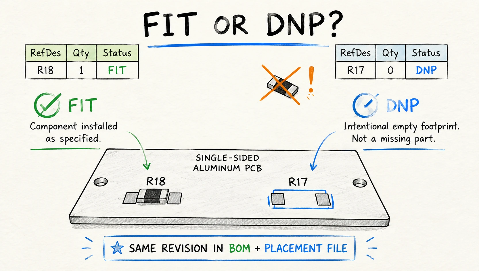 DNP marks an intentional empty footprint, so the BOM and placement file must use the same released revision.
There are two practical ways to release DNP locations.
Method 1: Keep the DNP row
Retain the component row, set Status = DNP or DNI, and use a build quantity of zero. This keeps the empty position visible and works when the assembler's system reads population status correctly.
Method 2: Send a fit-only BOM
Include only components that must be purchased and installed. Remove DNP positions from the production pick-and-place output, then record the empty option locations in the controlled variant or assembly drawing.
Altium's DNP guidance discusses explicit DNP entries and adding or removing parts across controlled design variants.
Either method works when every released file follows the same rule.
Do not leave quantity at 1 and hide DNP in a comment. Do not use a blank MPN or TBD as the only sign that the location stays empty.
And remember: a 0-ohm resistor is a real component. It is not a DNP instruction.
Control the LED, Not Just the Package and Color
Go back to the original BOM entry: “2835 LED, 4000 K.”
The factory knows the nominal package and color temperature. It still does not know which reel to order.
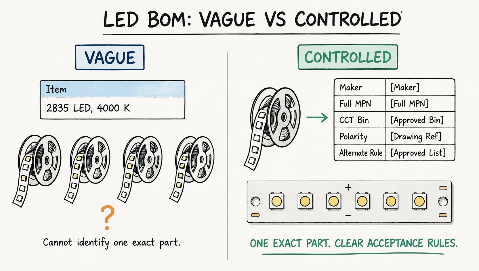 Package and nominal CCT do not identify one exact LED; add the full MPN and acceptance rules that the product actually controls.
For an LED aluminum board, start with the exact manufacturer and MPN. Add the remaining controls only when they affect acceptance of the finished product.
| LED or assembly detail | Include it when... | If it is unclear... |
|---|---|---|
| Exact LED manufacturer and MPN | The production LED is controlled | The wrong emitter family or ordering variant may be purchased |
| CCT or chromaticity bin | Color consistency matters | Boards or fixtures may show visible color differences |
| Minimum CRI | The lighting product specifies it | A substitute may not meet the color-rendering requirement |
| Flux bin | Module output is controlled | Finished light output may be uneven or too low |
| Forward-voltage bin | Circuit topology or current balance makes it relevant | Parallel strings may not share current as intended |
| Bin-mixing rule | One board, fixture, or lot must look consistent | Different bins may be mixed in the finished product |
| Cathode or anode reference | The component is polarity-sensitive | The LED may be placed in reverse |
| Approved alternate rule | Another LED may be considered | Optical, electrical, or thermal performance may change without approval |
| MSL or reflow reference | The selected LED family requires handling control | Moisture or reflow exposure may damage the component |
| Thermal or insulating hardware | The item is included in the assembly scope | A required interface or isolation item may be omitted |
LED makers use product-specific bin structures. The Lumileds LUXEON 3535L Color Line datasheet, for example, connects product identification with color, flux, or forward-voltage information for relevant variants. Cree LED's J Series Precision Dimming guide explains why forward-voltage control matters in some parallel-string designs.
Use the codes from the selected LED manufacturer's documentation. Do not invent a generic bin format.
Polarity should also be explicit. For example: “Cathode = PCB pad 1 / K mark shown on the released assembly drawing. Do not infer polarity from package appearance alone.”
The exact LED data sheet controls this detail. An ams OSRAM product datasheet, for example, documents polarity for that specific product—not for every LED with a similar package name.
Not every cost-sensitive LED board needs CCT, flux, and forward-voltage bin fields. A simple product may control only the maker, MPN, nominal CCT, and polarity. A fixture with tight color limits or parallel strings may need more.
Include the details that decide whether the finished board will be accepted. Leave the rest out.
For a single-sided aluminum PCB with SMT, clear LED identity, polarity, and substitution limits remove avoidable questions before assembly starts.
Copy This LED PCB Assembly BOM Example
Here is a compact example for a simple aluminum LED board. You can also download this pre-formatted Excel template (.xlsx) to populate your parts list directly:
| Line | RefDes | Qty/PCBA | Manufacturer | MPN | Description | Package | Status | Approved alternate or build note |
|---|---|---|---|---|---|---|---|---|
| 10 | D1-D24 | 24 | [LED maker] | [Full MPN] | White LED, 4000 K, CRI ≥90 | 2835 | FIT | Approved bin range; cathode per assembly drawing |
| 20 | R1,R2 | 2 | [Maker] | [Full MPN] | Current-setting resistor; value, tolerance, and power | 1206 | FIT | No unapproved value change |
| 30 | R3 | 0 | [Maker] | [Full MPN] | Optional configuration resistor | 0603 | DNP | Not fitted in Variant A |
| 40 | J1 | 1 | [Maker] | [Full MPN] | Two-position input connector | [Package] | FIT | Orientation per assembly drawing |
The bracketed values are examples. They are not Lumina standard component specifications.
A practical starting header is: Line, RefDes, Qty per PCBA, Manufacturer, MPN, Description, Package, Footprint, Status, Approved Alternate, Build Note.
Add distributor information, sourcing responsibility, mounting side, or process references only when the project needs them. More columns do not make the BOM safer by themselves.
Fix These BOM Mistakes Before Quotation
Most review questions come from ambiguity or conflict between files—not from a lack of spreadsheet decoration.
| Problem | What to do instead |
|---|---|
| Missing or shortened MPN | Use the complete manufacturer ordering code |
| Manufacturer and MPN do not match | Check both against the component maker's data |
| Quantity does not match the RefDes count | Recount the fitted designators on each row |
| Panel or order quantity appears in the board quantity column | Use Qty per PCBA only |
| DNP is hidden in a comment | Use a dedicated status field or a controlled fit-only BOM |
| Several MPNs and “equivalent” share one cell | List exact approved alternatives separately |
| LED is identified only by package and color | Add the exact MPN and the optical limits the product controls |
| Package does not match the released footprint | Check package, footprint, and polarity together |
| BOM and placement data come from different revisions | Release one named revision and variant together |
| PDF is the only editable BOM source | Provide clean XLSX or CSV when the assembler accepts it |
One final cross-check catches several of these problems at once: compare the fitted RefDes in the BOM with the RefDes in the production pick-and-place file. Missing, duplicated, and extra locations become much easier to spot.
Run This Check Before You Send the BOM
- The PCBA number, revision, and build variant are identified.
- Every fitted RefDes appears once.
- Quantity equals the number of fitted RefDes on each row.
- Controlled parts have the correct manufacturer and complete MPN.
- Description, MPN, and package agree.
- Package and released PCB footprint have been checked together.
- DNP or DNI locations are unambiguous.
- Approved alternatives are listed separately rather than as “equivalent.”
- LED bin and polarity notes are included where the product requires them.
- BOM, pick-and-place data, and assembly drawing use the same revision.
- The file follows the assembler's requested format.
A complete assembly request normally needs more than a BOM. Include the fabrication files, placement data, finished quantity, sourcing responsibility, and applicable test requirements. Our PCB assembly quote checklist covers that wider package.
Planning a single-sided aluminum LED board with SMT assembly? Send Lumina the Gerber files, BOM, placement data, quantity, and relevant LED notes. We can review the package and mark unclear project details before quotation or production starts.
Need a quotation?
Send Gerber files and basic specifications. We reply within 1 business day.
Ask for Quote